Line arrangement for a motor vehicle having at least one line which is configured as a textile hose

a technology of textile hoses and motor vehicles, which is applied in the direction of vehicles, machines/engines, synthetic resin layered products, etc., can solve the problems of high material cost, weight and manufacturing cost, and the need for expensive additional elements to be installed, so as to improve the functionality

Active Publication Date: 2019-06-11
MAN TRUCK & BUS AG
View PDF26 Cites 0 Cited by
  • Summary
  • Abstract
  • Description
  • Claims
  • Application Information

AI Technical Summary

Benefits of technology

[0005]It is an object of the invention to provide a possibility for overcoming the abovementioned disadvantages and, as an alternative or in addition, to provide a line arrangement with improved functionality, in particular with regard to thermodynamic and / or safety aspects.
[0016]It is likewise possible that the textile hose is of dimensionally stable configuration. To this end, the textile hose can have, for example, a spiral, with the result that the spiral expediently serves to achieve the dimensional stability.
[0018]The spiral is preferably a plastic spiral. It is possible that the textile hose encloses an inner line, for example a stainless steel line, and / or a hydraulic hose, and the inner line serves to conduct the fluid medium, with the result that the textile hose expediently does not come into contact with the medium in the normal operating state. However, in the case of a leak of the inner line (for example, leak, burst, etc.), the textile hose can ensure that the medium from the inner line is retained and / or is conducted to a predefined, in particular non-critical, location. However, the inner line can also be configured as a textile hose that is expediently as disclosed herein, with the result that the outer textile hose expediently does not come into contact with the medium in the normal operating state. However, in the case of a leak of the inner line which is likewise configured as a textile hose (for example, leak, burst, etc.), the outer textile hose can ensure that the medium from the inner line which is configured as a textile hose is retained and / or is conducted to a predefined, in particular non-critical, location.
[0032]It is possible that the textile hose is of elastic configuration, for example in its longitudinal and / or radial direction, and can therefore expediently expand and contract.
[0035]A vacuum is usually produced during cooling of the medium in the line or lines, by way of which vacuum medium continues to flow out of a compensating container (expedient shutting-off operation). The textile hose can therefore be of elastic, for example non-dimensionally stable, configuration, with the result that it can contract, in particular, as a result of vacuum, as a result of which the compensating container can be, for example, of smaller dimensions or can even be dispensed with. The compensating container can be reduced in size, in particular, substantially by the amount, by which the textile hose can contract.

Problems solved by technology

Stainless steel lines have the disadvantage, in particular, that they are firstly intensive with regard to material costs, weight, and manufacturing costs (for example, three-dimensional bending of the line contour).
Secondly, expensive additional elements have to be installed, such as compensators for vibration decoupling and stainless steel cutting ring fittings for connecting the stainless steel pipes.
High pressure hoses from the hydraulic field have, in particular, the disadvantage of low resistance to some ORC media and, moreover, a high weight.
In addition, they are expensive and less flexible on account of the inner construction, in particular on account of braided wire inserts.

Method used


Image

  • Line arrangement for a motor vehicle having at least one line which is configured as a textile hose
  • Line arrangement for a motor vehicle having at least one line which is configured as a textile hose
  • Line arrangement for a motor vehicle having at least one line which is configured as a textile hose

Examples


Embodiment Construction

[0048]The embodiments shown in the figures coincide in part, with the result that similar or identical parts are provided with the same reference numerals and reference is also made to the description and the figures of the other embodiments in order to explain them, so as to avoid repetitions.

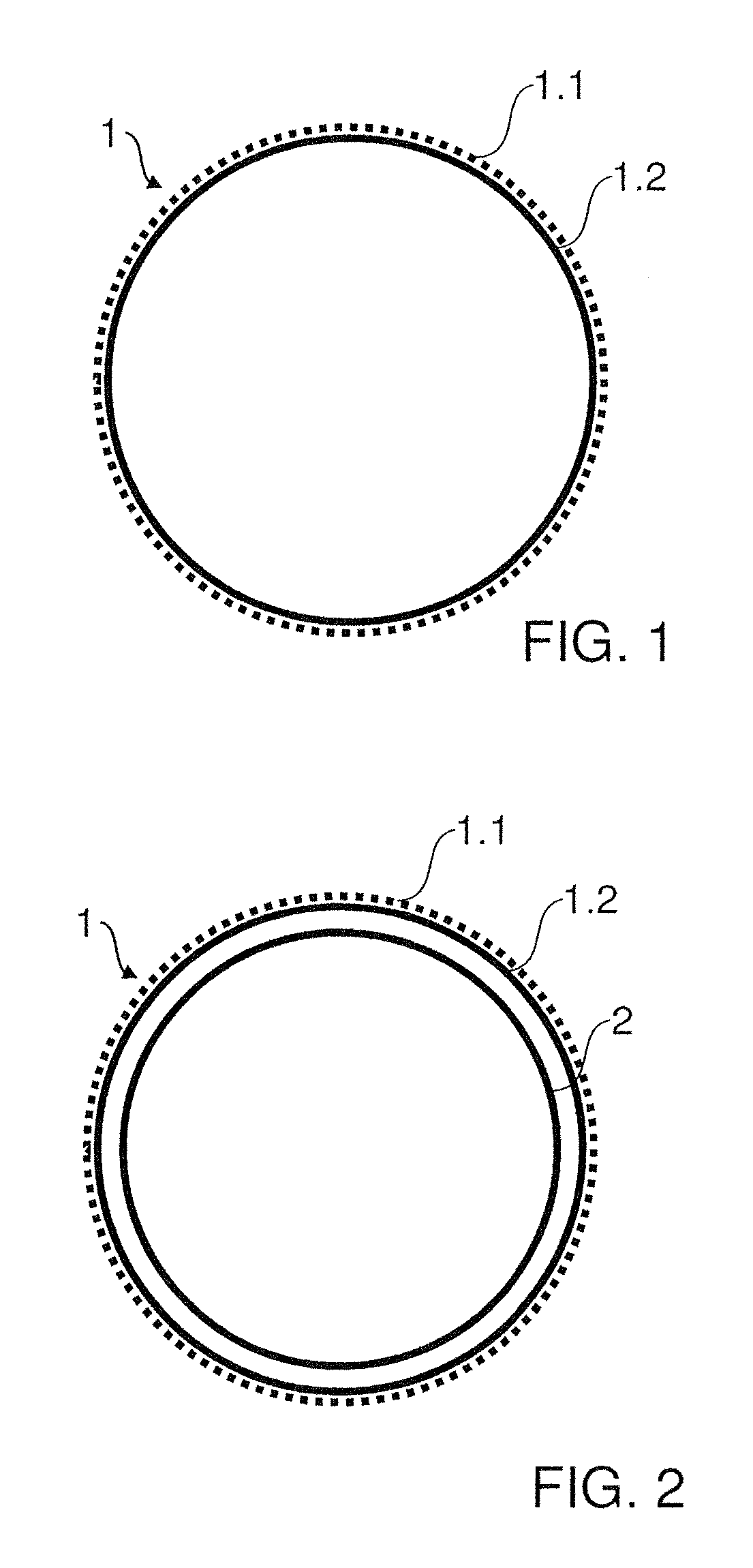
[0049]FIG. 1 shows a diagrammatic cross-sectional view of a line configured as a textile hose 1 for conducting a fluid medium. The textile hose 1 has a textile structure 1.1, in particular a woven textile structure, and a medium-resistant inner sheath 1.2. The textile structure 1.1 encloses the inner sheath 1.2. The inner sheath 1.2 serves to conduct and therefore to come into contact with the fluid medium and is expediently configured to ensure the sealed state of the textile hose 1. To this end, the inner sheath 1.2 can be configured from an elastomer. In contrast, the textile structure 1.1 expediently serves to absorb the forces of the pressure of the fluid medium.

[0050]In the embodiment sh...


PUM

PropertyMeasurementUnit
pressure-resistantaaaaaaaaaa

Abstract

A line arrangement for a motor vehicle, preferably for a waste heat utilization system of a motor vehicle. The line arrangement includes one or more lines for conducting a fluid medium and is distinguished, in particular, by the fact that at least one line comprises at least one textile hose or is configured as at least one textile hose, and the textile hose has a textile structure and an inner sheath.

Description

BACKGROUND OF THE INVENTION[0001]1. Field of the Invention[0002]The invention relates to a line arrangement for a motor vehicle, preferably a commercial vehicle, in particular a lorry or an omnibus. The line arrangement is configured, in particular, for a waste heat utilization system for the conversion of waste heat of an internal combustion engine into utilizable energy.[0003]2. Description of the Related Art[0004]In motor vehicles, media, sometimes also flammable media, often have to be guided past internal combustion engines, which are hot during operation, with constricted space conditions. In systems for waste heat utilization (Waste Heat Recovery=WHR) of internal combustion engines, steam circuit processes (for example, Clausius Rankine Cycle=CRC, Organic Rankine Cycle=ORC, etc.) are used. Here, a circuit medium is brought to a high pressure level in a feed pump and is evaporated and superheated in an evaporator. The steam is subsequently fed to an expansion machine that conv...

Claims


Application Information

Patent Timeline
Patent Type & Authority Patents(United States)
IPC IPC(8): F01K23/10F16L59/153B32B25/10B32B15/18B32B1/08B60R16/08D03D3/02F16L11/02F16L11/20B32B5/02B32B5/04B32B27/12B32B3/08F16L11/12
CPCF01K23/10B32B3/08B32B5/02B32B5/024B32B5/04B32B15/18B32B25/10B32B27/12B60R16/08D03D3/02F16L11/02F16L11/20F16L59/153B32B1/08F16L11/12B32B2274/00B32B2307/304B32B2307/306B32B2307/51B32B2307/56B32B2307/7242B32B2307/734B32B2597/00B32B2605/08F16L11/082F02G5/00F16L9/14F16L59/14B60H1/00
Inventor RAAB, GOTTFRIEDKLAMMER, JOSEFROBAUSCH, STEFAN
Owner MAN TRUCK & BUS AG
Why Eureka
Try Eureka