Drive system of a wind turbine

a technology of drive system and wind turbine, which is applied in the direction of gearing details, machines/engines, gearing, etc., can solve the problems of large space requirement of the drivetrain, large diameter of the rotor of the generator, and complex structure, so as to achieve the effect of significantly simplifying the separation point between the transmission and the generator

Active Publication Date: 2019-06-11
FLENDER GMBH
View PDF31 Cites 0 Cited by
  • Summary
  • Abstract
  • Description
  • Claims
  • Application Information

AI Technical Summary

Benefits of technology

[0022]It is only in the combination of the features medium-speed, modular or partially integrated and slide bearings for both the main components transmission and generator that the technical advantage of the present invention has its full effect.
[0023]In particular, it is advantageous in drivetrains, in particular, modular-constructed medium-speed drivetrains, to replace the roller bearing which is provided at the separation point between the generator and the transmission with a slide bearing. This separation point between the transmission and the generator can thereby be significantly simplified, since a servicing facility no longer has to be made available.
[0024]EP 2 508 753 A1 (Siemens; Winergy) 2012 Oct. 10, EP 2 508 754 A1 (Siemens) 2012 Oct. 10, EP 2 508 777 A1 (Siemens) 2012 Oct. 10, EP 2 541 096 A1
[0025](Siemens) 2013 Jan. 02, EP 2 541 058 A1 (Siemens) 2013 Jan. 02 and EP 2 573 386 A1 (Siemens; Winergy) 2013 Mar. 27, describe drive systems. These systems are particularly suitable therefor that both the transmission and the generator are mounted in slide bearings.
[0026]In the following description, several examples of a drive system are described. These systems are particularly suitable therefor that both the transmission and the generator are mounted in slide bearings.
[0027]A drivetrain for a wind energy system having a transmission which has a transmission housing and is connected or connectable via an input shaft to a wind rotor, and a generator which has a generator housing which is firmly connected to the transmission housing and in which at least one stator and at least one rotor are provided, wherein the rotor is coupled to an output shaft of the transmission mounted by means of bearings on the transmission housing, said output shaft running faster during operation than the input shaft, characterized in that the generator has a generator shaft arranged coaxially with the output shaft of the transmission and mounted on the generator housing by means of bearings, said generator shaft being connected via connecting flanges to the output shaft of the transmission, wherein an electrical insulation is provided between the connecting flanges, in that a labyrinth seal or a gap seal is provided between the transmission housing and the generator housing and in that, in sequence, the bearings, the labyrinth seal or gap seal and the connecting flange are held on the output shaft and following thereafter, the connecting flange, the rotor and the bearing are held on the generator shaft.

Problems solved by technology

It is disadvantageous herein that the drivetrain requires a relatively large amount of space and due to the large number of components, has a complex structure.
A disadvantage herein is that due to the high torque that is conducted directly into the generator from the wind rotor, the generator and, in particular, the rotor of the generator have a comparatively large diameter.
This is associated with relatively large dimensions and a large weight of the drivetrain.
The direct connection of the transmission to the generator leads to a substantial shortening of the drivetrain as compared with the “non-integrated drivetrain”.
In all drivetrain configurations, roller bearings are one of the substantial causes of failures in a wind turbine.
However, so far, the generators continue to be equipped with roller bearings so that significant expenditure must be made for the maintenance and serviceability of these roller bearings: to date, for modular construction medium-speed drivetrains, a separation point between the generator and the transmission has been provided.

Method used


Image

  • Drive system of a wind turbine
  • Drive system of a wind turbine
  • Drive system of a wind turbine

Examples


Embodiment Construction

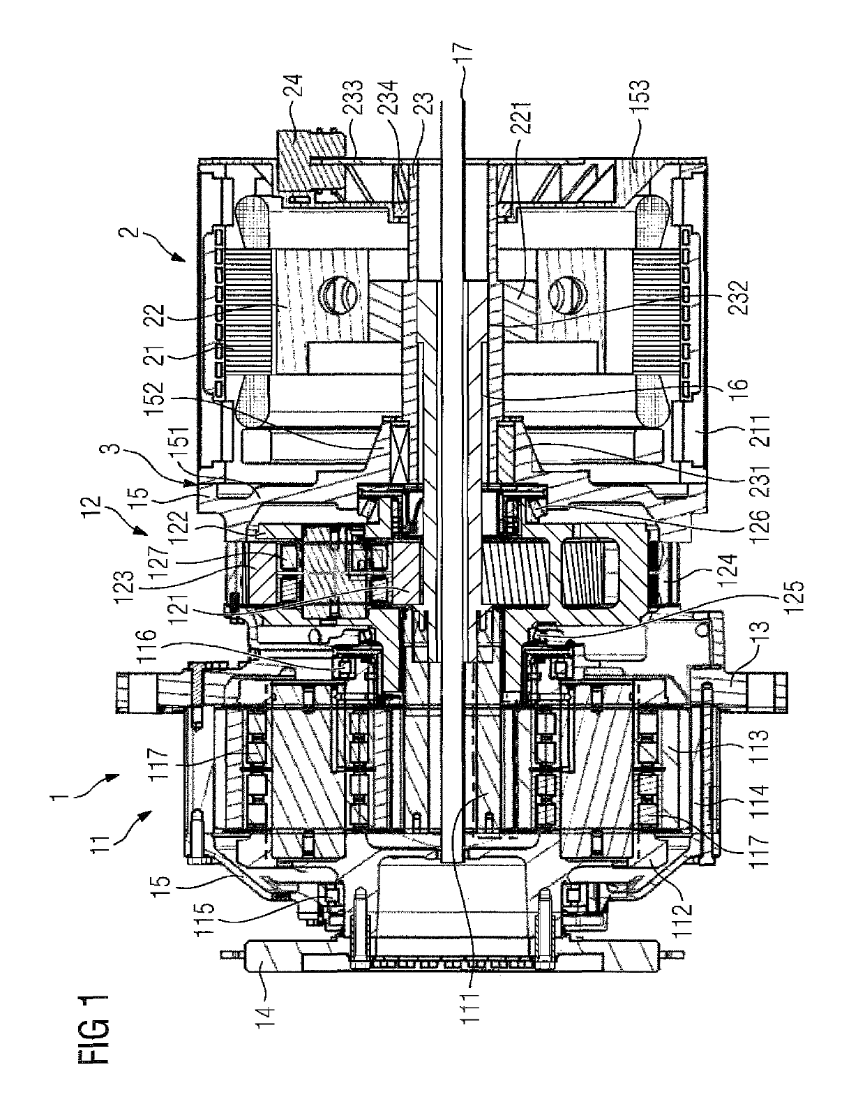
[0081]FIG. 1 shows a drive system for a wind turbine which has a transmission unit 1 with a first 11 and a second planetary gear stage 12 in a coaxial construction. Herein, each planetary gear stage 11, 12 comprises a ring gear 114, 124, a plurality of planet gears 113, 123, a planet carrier 112, 122 and a sun gear 111, 121. “Coaxial construction” means that the rotation axes of the sun gears 111, 121 of both planetary gear stages 11, 12 coincide.

[0082]The transmission unit 1 is connected via an output shaft 16 of the transmission unit 1 to a generator unit 2 and is arranged together therewith in a transmission housing 15. Between the transmission unit 1 and the generator unit 2, the transmission housing 15 has a parting line 3 along which the transmission unit 1 and the generator unit 2 can be parted. An input shaft formed on the planet carrier 112 of the first planetary gear stage 11 is associated with the transmission unit 1, said input shaft having a coupling flange 14 which is ...


PUM


Abstract

A drive system of a wind turbine includes a transmission gear configured to be connected to a wind rotor shaft, the transmission gear having a first planetary gear set and a second planetary gear set, and a generator downstream of the transmission gear. The transmission gear and the generator are mounted in sliding bearings.

Description

CROSS-REFERENCES TO RELATED APPLICATIONS[0001]This application is the U.S. National Stage of International Application No. PCT / EP2015 / 058131, filed Apr. 15, 2015, which designated the United States and has been published as International Publication No. WO 2015 / 158753 which claims the priority of European Patent Application, Serial No. 14177650.0, filed Jul. 18, 2014 and German Patent Application, Serial No. 10 2014 207 230.1, filed Apr. 15, 2014 pursuant to 35 U.S.C. 119(a)-(d).BACKGROUND OF THE INVENTION[0002]The present invention relates to a drive system of a wind turbine.[0003]Drive trains for wind turbines are known and are used to convert the rotational energy of a wind rotor set in motion by the wind, into electrical energy by means of a generator coupled to the wind rotor. Herein, the wind rotor typically reaches rotary speeds in the region of approximately 10 to 20 min−1.[0004]A large proportion of the existing wind turbines is equipped with rapidly rotating generators hav...

Claims


Application Information

Patent Timeline
Patent Type & Authority Patents(United States)
IPC IPC(8): F16H1/46H02K7/18F03D9/25H02K7/116F03D15/10F03D15/00F03D80/70F16H57/04H02K5/20F16H57/08
CPCF03D15/00F03D15/10F03D80/70F16H1/46H02K7/116H02K7/1838F03D9/25Y02E10/725F05B2240/54F05B2260/40311F05B2260/98F16H57/0471F16H57/082F16H2057/085H02K5/20Y02E10/72
Inventor DEICKE, MATTHIASTENBROCK, STEFAN
Owner FLENDER GMBH
Why Eureka
Try Eureka