Tilt sensor

a tilt sensor and sensor technology, applied in the field of tilt sensors, can solve the problems of increasing the risk of exposure to hazardous materials, inefficient and/or hazardous monitoring using human labor, and the current tilt sensor is problematic, so as to prevent damage to the components, effectively seal the chamber, and avoid the effect of being damaged

Active Publication Date: 2019-06-11
SCHAFER PHILIP +2
View PDF41 Cites 0 Cited by
  • Summary
  • Abstract
  • Description
  • Claims
  • Application Information

AI Technical Summary

Benefits of technology

[0011]Changing the contours of the low point affects the mobility of the metallic ball and thus the sensitivity of the tilt sensor. For example, increasing the slope of the surfaces defining the low point increases the amount of tilt needed to displace the metallic ball from its point of repose. Decreasing the slope allows the metallic ball more freedom of movement. Thus, in other embodiments, the low point may be a separate component, such as a molded insert, that is able to be removed from the chamber and replaced with a low point with different contours, thereby changing the sensitivity of the tilt sensor.
[0016]Depending on the types of materials used to construct the prox holder and chamber, it may be desirable to provide a spacer between the prox holder and prox holder seat to prevent damage to the components and otherwise provide a proper fit between the prox holder and prox holder seat. For example, in the threaded circular prox holder configuration described above, if the prox holder is constructed of a relatively pliable plastic and the prox holder seat a rigid metal, an annular spacing mechanism may be inserted adjacent to the prox holder seat such that the prox holder may be properly installed within the chamber without risk of being damaged.
[0017]Because the tilt sensor is likely to be used in harsh environments, it may be necessary or desirable to protect the metallic ball and other components from interference or contamination by effectively sealing the chamber from infiltration by fluids or solids. Where the chamber is formed with more than one piece, this can be accomplished through the incorporation of seals, such as rubber o-rings, placed at the interface of the chamber pieces. If the metallic ball is contained within a sub-chamber, additional gaskets and seals may be used within the device to further protect the sub-chamber from infiltration.

Problems solved by technology

It is often inefficient and / or hazardous to use human labor to monitor the dispensing process to determine when to restrict or otherwise modify the flow.
For example, chemical transport containers are often opaque, requiring a person to monitor the container capacity at close range, increasing the risk for exposure to hazardous materials.
Current tilt-sensing devices are problematic.
For example, devices incorporating mercury switches are inherently dangerous due to the presence of mercury, limiting their application.
Similarly, devices incorporating limit switches acted on by the weight of a ball contained within the device are inadequate as, in practice, the ball does not consistently trigger the switch as designed.
These devices are prone to failure due to contamination and excess wear of certain components, such as the transmitting wires.
Because these devices are largely self-contained and rigidly assembled, users are unable to disassemble the devices to attempt to repair them.

Method used


Image

  • Tilt sensor
  • Tilt sensor
  • Tilt sensor

Examples


Embodiment Construction

[0029]While the presently disclosed inventive concept(s) is susceptible of various modifications and alternative constructions, certain illustrated embodiments thereof have been shown in the drawings and will be described below in detail. It should be understood, however, that there is no intention to limit the inventive concept(s) to the specific form disclosed, but, on the contrary, the presently disclosed and claimed inventive concept(s) is to cover all modifications, alternative constructions, and equivalents falling within the spirit and scope of the inventive concept(s) as defined in the claims.

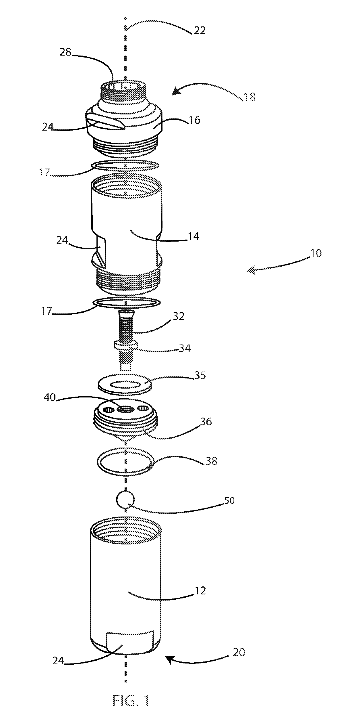
[0030]FIG. 1 is an exploded view of one embodiment of the tilt sensor 10. In the embodiment shown, the main body of the tilt sensor 10 is constructed of three pieces: a ball carrier 12, a throat 14, and a cap 16. In this embodiment, the three pieces are connected through the use of complementary threading, though other methods of construction will be known to those skilled in the art. T...


PUM


Abstract

A tilt sensor for signaling when the tilt sensor is not vertical. The tilt sensor includes a metallic ball that is free to move and capable of resting at a low point when the tilt sensor is vertical. A proximity sensor directed at the low point communicates when the metallic ball has deviated from its position of repose, indicating that the sensor is no longer vertical.

Description

TECHNICAL FIELD[0001]The presently disclosed technology relates to a tilt sensor. More particularly, the present invention uses an inductive sensor to indicate when the device has deviated from a vertical position.BACKGROUND[0002]Free flowing materials, such as grain, chemicals, and cement, among many others, are commonly dispensed into piles or containers for transportation, use, and / or storage. It is often inefficient and / or hazardous to use human labor to monitor the dispensing process to determine when to restrict or otherwise modify the flow. For example, chemical transport containers are often opaque, requiring a person to monitor the container capacity at close range, increasing the risk for exposure to hazardous materials. Thus, attempts have been made to monitor the dispensing process using mechanical methods, such as tilt-sensing devices.[0003]Current tilt-sensing devices are problematic. For example, devices incorporating mercury switches are inherently dangerous due to t...

Claims


Application Information

Patent Timeline
Patent Type & Authority Patents(United States)
IPC IPC(8): G01C9/06G01C9/10
CPCG01C9/06G01C9/10G01C2009/107G01C2009/064
Inventor SCHAFER, PHILIPWALTERS, ANTON MMULLER, BRENT
Owner SCHAFER PHILIP
Why Eureka
Try Eureka