Image forming apparatus

a technology of forming apparatus and forming belt, which is applied in the direction of electrographic process apparatus, thin material handling, instruments, etc., can solve the problems of fatigue failure, rigidity drop, stress concentration load, etc., and achieve the effect of reducing the concentration of load

Active Publication Date: 2019-06-18
CANON KK
View PDF17 Cites 4 Cited by
  • Summary
  • Abstract
  • Description
  • Claims
  • Application Information

AI Technical Summary

Benefits of technology

[0008]A principal object of the present invention is to provide an image forming apparatus capable of alleviating concentration of a load at a widthwise end portion of an endless belt in a constitution including the endless belt stretched by a plurality of states.

Problems solved by technology

In such a belt feeding device, a problem of “belt shift” such that the belt shifts toward an end portion side of either of the stretching rollers with respect to a rotational axis direction during feeding (traveling) of the belt due to accuracy of outer diameters of the stretching roller, accuracy of relative alignment between the respective stretching rollers, and the like has been known.
However, in the case where lifetime extension or cost reduction of the belt are promoted, the following problem occurs in some cases.
This stress concentration loads to fatigue failure (crack) of the belt in some cases when an amount of repetitive use of the belt increases, and is a problem when the lifetime extension is promoted.
Further, in the case where a thickness of the belt is made thin for reducing the cost of the belt or the like, rigidity of the belt lowers, and therefore, loads to the above-described fatigue failure earlier in some cases.

Method used


Image

  • Image forming apparatus
  • Image forming apparatus
  • Image forming apparatus

Examples


embodiment 1

1. General Structure and Operation of Image Forming Apparatus

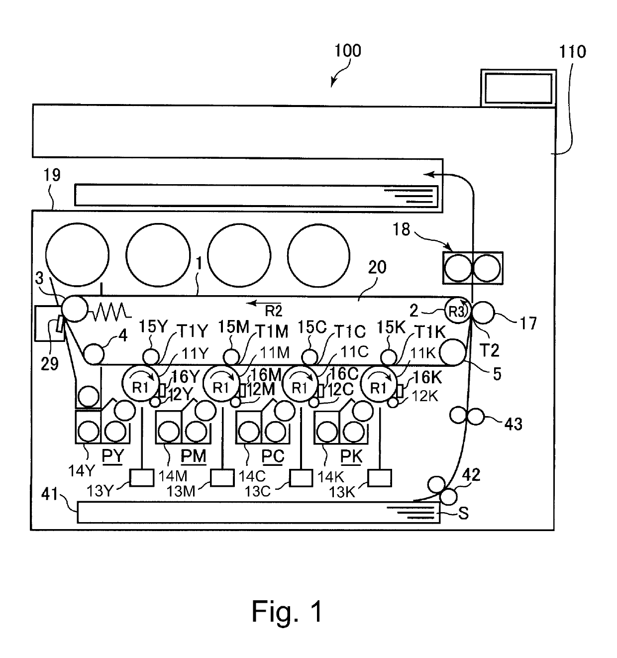
[0019]FIG. 1 is a schematic sectional view of an image forming apparatus 100 in this embodiment.

[0020]The image forming apparatus 100 in this embodiment is a tandem-type multi-function machine which is capable of forming a full-color image using an electrophotographic type and which employs an intermediary transfer type. The multi-function machine has functions of a copying machine, a printer and a facsimile machine.

[0021]The image forming apparatus 100 includes, as a plurality of image forming portions (stations), four image forming portions (stations) PY, PM, PC and PK for forming images of color of yellow (Y), magenta (M), cyan (C) and black (K), respectively. These four image forming portions PY, PM, PC and PK are provided and arranged along a movement direction of an intermediary transfer belt 1 described later. Incidentally, as regards elements having the same or corresponding constitutions in the respective image fo...

embodiment 2

[0071]Another embodiment of the present invention will be described. Basic constitutions and operations of a belt feeding device and an image forming apparatus in this embodiment are the same as those in Embodiment 1. Accordingly, in this embodiment, elements having the same or corresponding functions and constitutions as those in Embodiment 1 are represented by the same reference numerals or symbols, and will be omitted from detailed description.

[0072]FIG. 7 is a schematic sectional view of an intermediary transfer belt unit 20 in this embodiment. In this embodiment, a winding angle of the intermediary transfer belt 1 about the idler roller 4 is θ1. Further, a winding angle of the intermediary transfer belt 1 about the upstream roller 5 is θ2. Further, a winding angle of the intermediary transfer belt 1 about the driving roller 2 is θ3. The winding angle refers to an angle (in a side corresponding to a region where the belt is wound about the associated roller) formed between lines...


PUM


Abstract

An image forming apparatus includes an image forming portion, an endless belt and a plurality of stretching rollers. The stretching rollers includes a tiltable steering roller, a sliding member, a first stretching roller having a smallest diameter, and a second stretching roller having a largest diameter of the diameters. With respect to rotational axis directions of the stretching rollers, lengths of contact portions of the stretching rollers with the belt are shorter than a width of the belt, the length of the contact portion of the first stretching roller with the belt is a first length, the length of the contact portion of the second stretching roller with the belt is a second length shorter than the first length, and end positions of the contact portions of the first and second stretching rollers with respect to the rotational axis direction are different from each other.

Description

FIELD OF THE INVENTION AND RELATED ART[0001]The present invention relates to an image forming apparatus including a belt feeding device for feeding an endless belt stretched by a plurality of stretching rollers.[0002]Conventionally, in the image forming apparatus of an electrophotographic type or an electrostatic recording type, the belt feeding device including the endless belt stretched by the plurality of stretching rollers is used. The belt is used as a feeding member for carrying and feeding a toner image or carrying and feeding a recording material on which the toner image is formed. As the feeding member for carrying and feeding the toner image, a belt-shaped electrophotographic photosensitive member (photosensitive belt), an intermediary transfer member (intermediary transfer belt) for carrying and feeding the toner image in order to transfer the toner image from the photosensitive member onto the recording material, and the like member are used. Further, as the feeding memb...

Claims


Application Information

Patent Timeline
Patent Type & Authority Patents(United States)
IPC IPC(8): B65H5/02G03G15/16G03G15/00G03G15/08
CPCB65H5/021B65H5/025G03G15/1615G03G15/6529B65H2403/25B65H2404/253B65H2404/2511B65H2801/06G03G15/0879G03G2215/00168G03G2215/0132G03G15/16
Inventor NAKAJIMA, TAKAO
Owner CANON KK
Why Eureka
Try Eureka