A Binary Nozzle Throat Area Control Mechanism

A binary nozzle and area technology, which is applied to machines/engines, jet propulsion devices, etc., can solve the problems of unsuitable binary nozzles, large required space, and large stroke range, and achieve the realization of binary nozzle throats. The effect of track area control, simple structure, and few moving joints

Active Publication Date: 2015-08-12
AECC SHENYANG ENGINE RES INST
View PDF5 Cites 0 Cited by
  • Summary
  • Abstract
  • Description
  • Claims
  • Application Information

AI Technical Summary

Problems solved by technology

Among the two methods, the first one requires the actuator to have a larger stroke range, while the second one has a bulky structure and requires a large space. Both methods are not suitable for the control of the throat area of ​​the binary nozzle.

Method used


Image

  • A Binary Nozzle Throat Area Control Mechanism
  • A Binary Nozzle Throat Area Control Mechanism
  • A Binary Nozzle Throat Area Control Mechanism

Examples


Embodiment 1

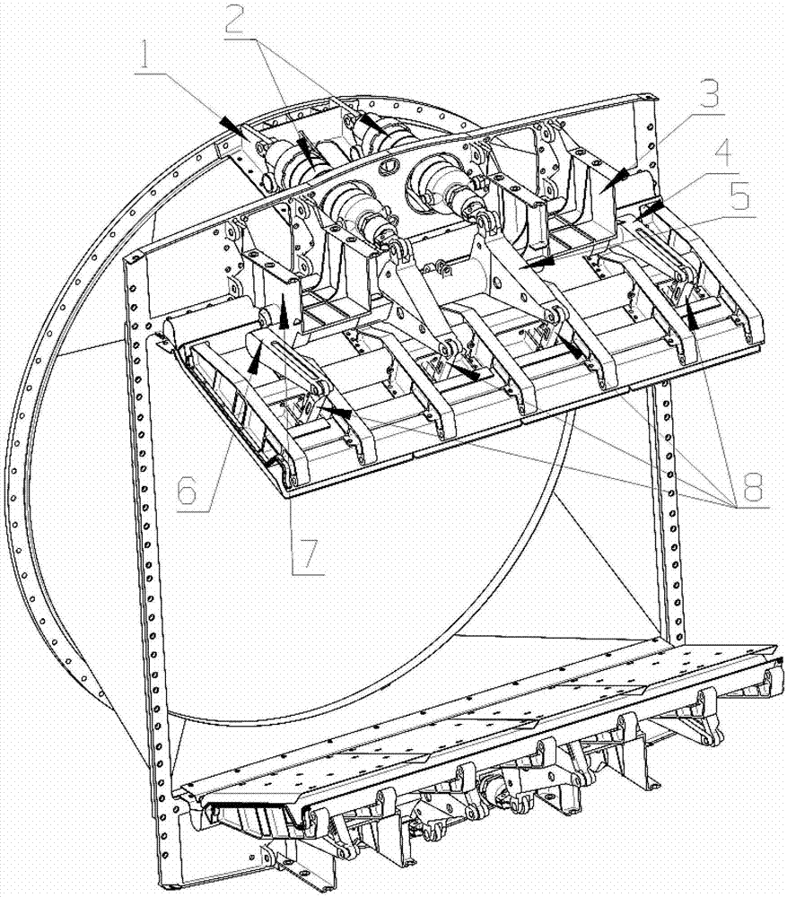
[0022] This embodiment provides a binary nozzle throat area control mechanism, which is characterized in that it includes a drive mechanism and a rocker link mechanism, specifically:

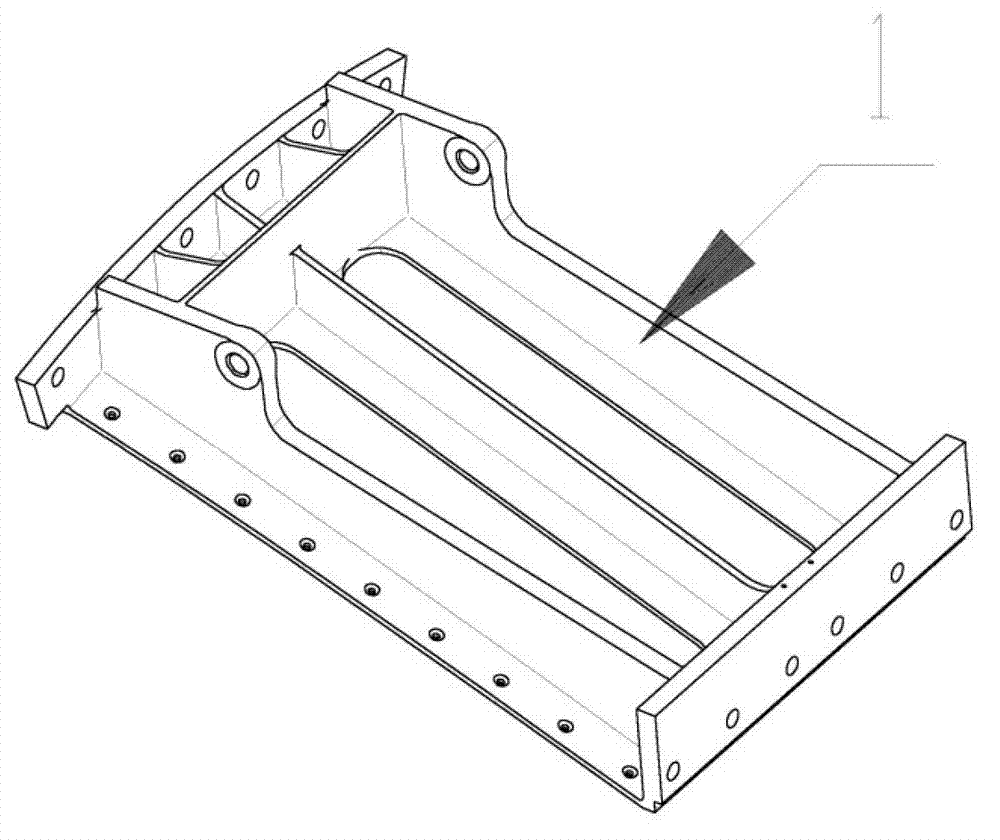
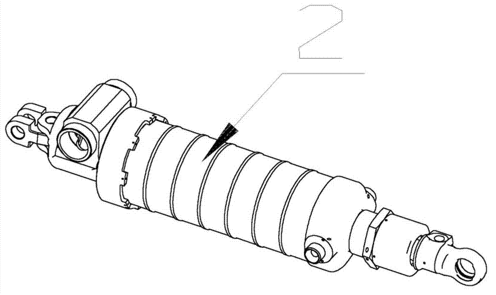
[0023] The driving mechanism includes a mounting base 1 and an actuator 2, wherein the mounting base 1 is fixed on the cylinder body of the binary nozzle; one end of the actuator 2 is hinged to the mounting base 1, and the other end is hinged to the active rocker arm 5;

[0024] The rocker link mechanism includes a first bracket 3, a first follow-up rocker arm 4, an active rocker arm 5, a second follow-up rocker arm 6, a second support 7 and a connecting rod 8, wherein the first support 3, the second support 7 They are respectively fastened to the main body of the nozzle; the first follow-up rocker arm 4 and the second follow-up rocker arm 6 pass through the first support 3 and the second support 7 respectively, and the cylindrical ends of the two are respectively connected to the two ends of the...

Embodiment 2

[0028] This embodiment provides a binary nozzle throat area control mechanism, which is characterized in that it includes a drive mechanism and a rocker link mechanism, specifically:

[0029] The driving mechanism includes a mounting base 1 and an actuator 2, wherein the mounting base 1 is fixed on the cylinder body of the binary nozzle; one end of the actuator 2 is hinged to the mounting base 1, and the other end is hinged to the active rocker arm 5;

[0030] The rocker link mechanism includes a first bracket 3, a first follow-up rocker arm 4, an active rocker arm 5, a second follow-up rocker arm 6, a second support 7 and a connecting rod 8, wherein the first support 3, the second support 7 They are respectively fastened to the main body of the nozzle; the first follow-up rocker arm 4 and the second follow-up rocker arm 6 pass through the first support 3 and the second support 7 respectively, and the cylindrical ends of the two are respectively connected to the two ends of the...

Embodiment 3

[0034] This embodiment provides a binary nozzle throat area control mechanism, which is characterized in that it includes a drive mechanism and a rocker link mechanism, specifically:

[0035] The driving mechanism includes a mounting base 1 and an actuator 2, wherein the mounting base 1 is fixed on the cylinder body of the binary nozzle; one end of the actuator 2 is hinged to the mounting base 1, and the other end is hinged to the active rocker arm 5;

[0036] The rocker link mechanism includes a first bracket 3, a first follow-up rocker arm 4, an active rocker arm 5, a second follow-up rocker arm 6, a second support 7 and a connecting rod 8, wherein the first support 3, the second support 7 They are respectively fastened to the main body of the nozzle; the first follow-up rocker arm 4 and the second follow-up rocker arm 6 pass through the first support 3 and the second support 7 respectively, and the cylindrical ends of the two are respectively connected to the two ends of the...


PUM


Abstract

The invention discloses a two-dimensional nozzle throat area control mechanism which comprises a driving mechanism and a rocker arm connecting rod mechanism. The two-dimensional nozzle throat area control mechanism is characterized in that the driving mechanism comprises an installation base and an actuator cylinder and the installation base is fixed to a two-dimensional nozzle cylinder body; one end of the actuator cylinder is hinged to the installation base and the other end of the actuator cylinder is hinged to a driving rocker arm; the rocker arm connecting rod mechanism comprises a first support, a first driven rocker arm, the driving rocker arm, a second driven rocker arm, a second support and a connecting rod; one cantilever end of the driving rocker arm is hinged to the actuator cylinder and the other cantilever end of the driving rocker arm is hinged to the connecting rod; one end of the connecting rod is hinged to the first driven rocker arm, the second driven rocker arm and the driving rocker arm and the other end of the connecting rod is hinged to a two-dimensional nozzle restraining adjusting sheet. The two-dimensional nozzle throat area control mechanism has the advantages of being simple and compact in structure, small in number of movement connecting pieces, wide in adjusting range and capable of enabling the control load to be dispersed to multiple points, effectively achieving control over the two-dimensional nozzle throat area, and meanwhile reducing the concentration degree of the load.

Description

technical field [0001] The invention relates to the field of aero-engine binary nozzle structures, in particular to a binary nozzle throat area control mechanism. Background technique [0002] There are mainly two types of traditional nozzle throat area control mechanisms, one is the adjustment method of the pull rod, which uses the actuator to drag the pull rod, and then drives the convergence adjustment piece to realize the control of the throat area; the other is the adjustment ring plus Arc cam or pull rod adjustment method, in which the actuator drags the adjustment ring, and the adjustment ring drives the convergence adjustment piece through the arc cam or pull rod to realize throat area control. Among the two methods, the first one requires the actuator to have a larger stroke range, while the second one has a bulky structure and requires a large space. Both methods are not suitable for the control of the throat area of ​​the binary nozzle. . In order to effectively...

Claims


Application Information

Patent Timeline
Patent Type & Authority Patents(China)
IPC IPC(8): F02K1/15
Inventor 叶留增贾东兵宁怀松
Owner AECC SHENYANG ENGINE RES INST
Why Eureka
Try Eureka