Supercharge Your Innovation With Domain-Expert AI Agents!

Method of performing autofocus, autofocus system, and camera comprising an autofocus module

a technology of autofocus and camera, applied in the direction of camera focusing arrangement, printers, instruments, etc., can solve the problems of inability to find the maximum, keep changing the focus motor position without being able to find, and annoying image wobbling, etc., to achieve better focused images, better focused images, and perform faster

Active Publication Date: 2019-06-18
AXIS
View PDF5 Cites 4 Cited by
  • Summary
  • Abstract
  • Description
  • Claims
  • Application Information

AI Technical Summary

Benefits of technology

[0010]It is an object of the present invention to provide a method of autofocusing which may provide better focused images. It is also an object of the invention to provide a method of autofocusing which may give better focused images also during panning, tilting and zooming. Another object of the invention is to provide a method of autofocusing which may be performed quicker than prior art methods.
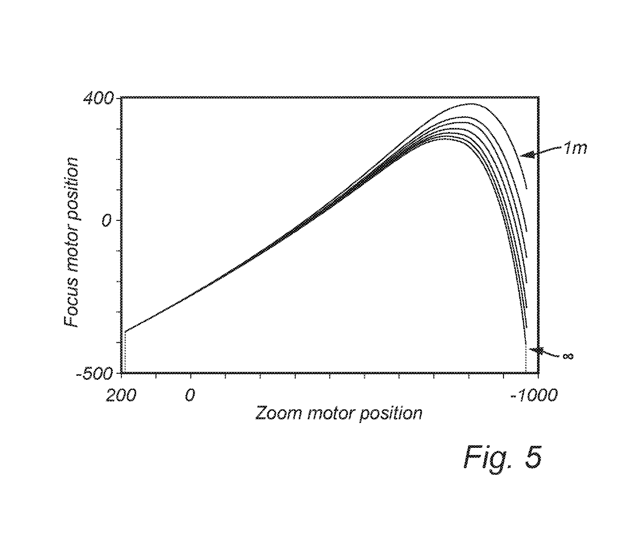
[0012]Using such an autofocus method, it is possible to make better use of the trace curves provided by the lens manufacturer. Even if the individual lens used on the camera does not behave exactly like the one for which the trace curves were calculated, and even if the production offset determined for the lens type during manufacture of the camera does not quite fit the individual lens, the calculation of the first correction factor based on the measured object distance and the distance corresponding to the focus motor position found by the passive autofocus algorithm makes it possible to follow a more suitable interpolated object distance trace curve during zooming. In this manner, better focused images may be provided during zooming. Thus, an operator watching a video sequence from the camera may get more information from the images, and may be relieved of the annoyance of watching blurry images. The operator may also be relieved of watching wobbling images during autofocusing using the passive autofocus algorithm, since a better starting point may speed up the search for focus using the passive autofocus algorithm.
[0014]Once the lens has reached the desired zoom position, the focus motor position found using the trace curves during the zooming operation may be used as a starting point for the passive autofocus algorithm, to determine a second determined focus position. Thus, proper focus may be found more quickly. This is also beneficial if a guard tour is ongoing, but the operator sees something of interest in the scene and interrupts the zooming operation. The latest focus motor position found using the correction factors and the trace curves may then be used as starting point for the passive autofocus algorithm, such that focused images may be provided quickly.
[0015]A second lookup object distance may be determined based on the second determined focus position, and a new correction factor may be calculated as a ratio between the second lookup object distance and the first object distance. In this manner, an updated correction factor making it easier to find a proper focus may be determined.
[0016]The method may also comprise zooming the lens to an intermediate zoom position between the first zoom position and a second zoom position, determining an intermediate depth of field for said intermediate zoom position, calculating an intermediate correction factor as a product of the first correction factor and a ratio between the intermediate depth of field and the first depth of field, calculating an intermediate object distance as a product of the first object distance and the intermediate correction factor, determining an intermediate focus position using the intermediate object distance. Hereby, autofocus positions may be determined at an intermediate zoom position, without having to perform a time-consuming passive autofocus algorithm. With such an approach, correction factors may be continually calculated during the zooming operation, such that good focus may be obtained by following suitable trace curves.
[0017]According to a variant, the method further comprises performing an intermediate autofocusing operation using the passive autofocus algorithm and using the intermediate focus position as a starting point for the algorithm, thereby determining an intermediate determined focus position. In this manner, an improved focus may be achieved also at zoom positions during the zoom operation from the first zoom position to the second zoom position. When time permits, such as when there is a high input frame rate to the passive autofocus algorithm, and the user requests a lower output frame rate, the passive autofocus algorithm may be used, with the latest determined focus position as starting point, thereby enabling possibly better focus than just by following the trace curves. This may for instance be done not for each frame during the zooming operation, but at regular or irregular intervals.

Problems solved by technology

In some situations, such as in low light conditions or in scenes with low contrast or with point-shaped light sources, it may be difficult to find a maximum for the contrast, and the autofocusing algorithm may end up “hunting”, which means it keeps changing focus motor position without being able to find a maximum.
Even in good light conditions, changes in focus occurring during the autofocus process, when the algorithm seeks the best focus motor position, may appear as annoying wobbling of the image.
A problem common to the passive and active methods is that the lens mounted on the camera may deviate from the one for which the trace curve was made, such that proper focus is not achieved using the focus position indicated for the determined object distance.
However, such offset testing is normally done only for two zoom positions, “tele” and “wide”, and only for focusing at infinity.
Further, for reasons of production economy, offset testing is in some cases done only once per lens type, and not for each individual lens.
The problems associated with known autofocusing methods are often aggravated in PTZ cameras.
Generally, the autofocusing process is not quick enough to provide focused images during a panning and / or tilting movement from one point in a monitored scene to another.
This blurriness during movement and zooming may be annoying to an operator watching a captured video sequence, for instance from a so-called “guard tour”, i.e. a pre-programmed sequence of panning, tilting and zooming operations performed to monitor various parts of a monitored area.
Important visual information may be lost to the operator during panning, tilting and zooming.

Method used


Image

  • Method of performing autofocus, autofocus system, and camera comprising an autofocus module
  • Method of performing autofocus, autofocus system, and camera comprising an autofocus module
  • Method of performing autofocus, autofocus system, and camera comprising an autofocus module

Examples


Embodiment Construction

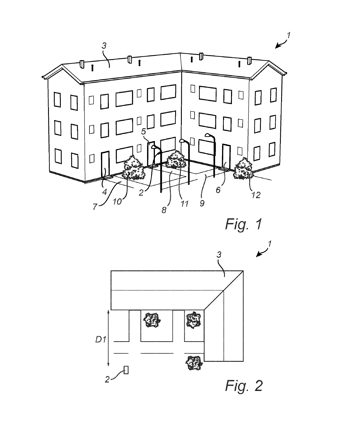
[0036]As seen in FIG. 1, a scene 1 is monitored using a camera 2. The scene 1 is shown from above in FIG. 2.

[0037]In the scene 1, there is building 3 with three doors 4, 5, 6. To each door, there is a respective path 7, 8, 9. Outside the building 3, there are three bushes 10, 11, 12.

[0038]The camera 2 is in this example a PTZ camera, i.e. a camera that is capable of panning, tilting and zooming. The same kind of functionality may be achieved using a camera having a zoom lens and mounting it on a so-called PT head, i.e. a device that pans and tilts an otherwise fixed camera.

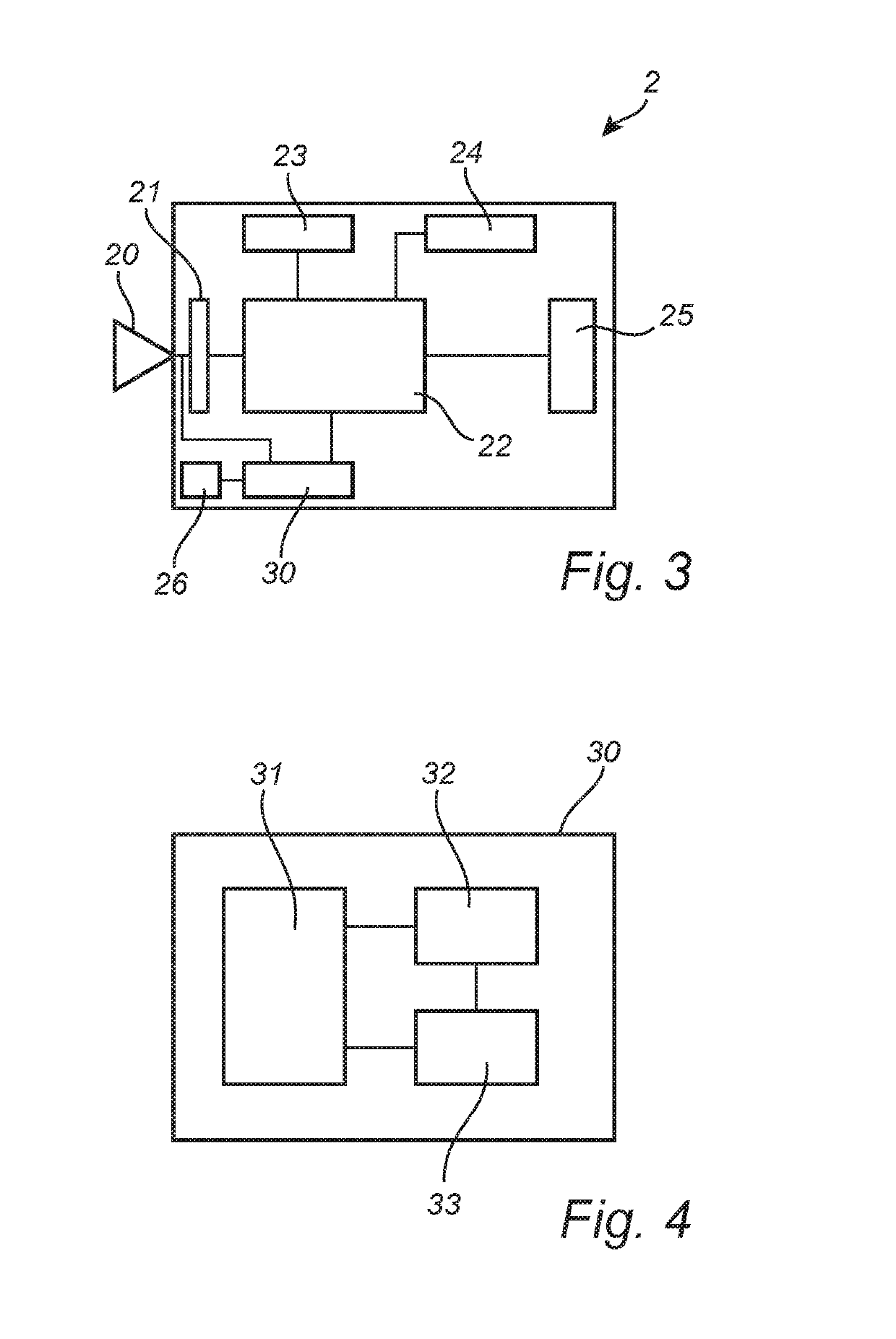
[0039]The camera 2 captures images of the scene 1, encodes them and transmits them as a video sequence to, e.g., a control centre, where the video sequence is decoded, such that an operator may watch the video sequence live. The video sequence may also be stored for later review. The camera 2 may also have on-board storage, for instance on an SD card, where video sequences may be stored for later retrieval.

[0040]T...


PUM


Abstract

Autofocusing a camera while zooming may include zooming the lens to a first zoom position, measuring a first object distance from the camera to an object on which to focus, determining a first focus start position using the first object distance, performing a first autofocus using the first focus start position as a starting point, thereby determining a first focus position. A first lookup object distance may be determined based on the first determined focus position. A first correction factor may be calculated as a ratio between the first lookup object distance and the first object distance. The lens may be zoomed to a second zoom position, and a second focus position may be determined using a second object distance based on the first object distance and a second correction factor based on depths of field at the second and first zoom positions.

Description

RELATED APPLICATION[0001]This application claims priority to European Application No. 16189024.9 filed Sep. 15, 2016, which is incorporated by reference herein.TECHNICAL FIELD[0002]The present invention relates to the field of autofocusing of cameras, and particularly autofocusing of PTZ cameras (i.e. cameras capable of panning, tilting and zooming.BACKGROUND[0003]Autofocus is a widely used functionality in cameras. It is used in handheld cameras as well as monitoring cameras, in still image cameras as well as video cameras. A number of different methods of performing autofocus are known, and they may generally be classified as either passive, active or hybrid methods. One known passive method is referred to as the max-contrast method or contrast detection method. In this method, the contrast between adjacent pixels in a captured image is studied, and by slightly changing focus around a starting point, a focus position of highest contrast is sought and, hopefully, found. The search ...

Claims


Application Information

Patent Timeline
Patent Type & Authority Patents(United States)
IPC IPC(8): G02B7/28G06K9/00G02B7/09H04N5/232G03B13/36
CPCG02B7/282G02B7/09G02B7/285G03B13/36G06K9/00624H04N5/23296H04N5/232121G03B2205/0046H04N23/67H04N23/671H04N23/69G03B3/02G03B13/20
Inventor NYSTROM, JOHANXU, CAN
Owner AXIS
Features
  • R&D
  • Intellectual Property
  • Life Sciences
  • Materials
  • Tech Scout
  • Unparalleled Data Quality
  • Higher Quality Content
  • 60% Fewer Hallucinations
Learn More