
Crystal oscillator

a crystal oscillator and surface mount technology, applied in oscillator generators, pulse automatic control, electrical equipment, etc., can solve problems such as degrading the hysteresis characteristics of laminated crystal oscillators

Active Publication Date: 2019-06-25
NIHON DEMPA KOGYO CO LTD
View PDF7 Cites 0 Cited by
  • Summary
  • Abstract
  • Description
  • Claims
  • Application Information

AI Technical Summary

Benefits of technology

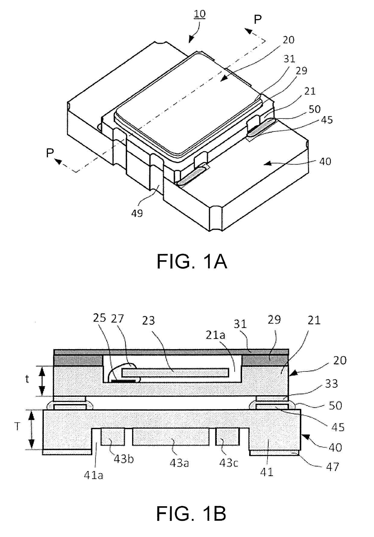
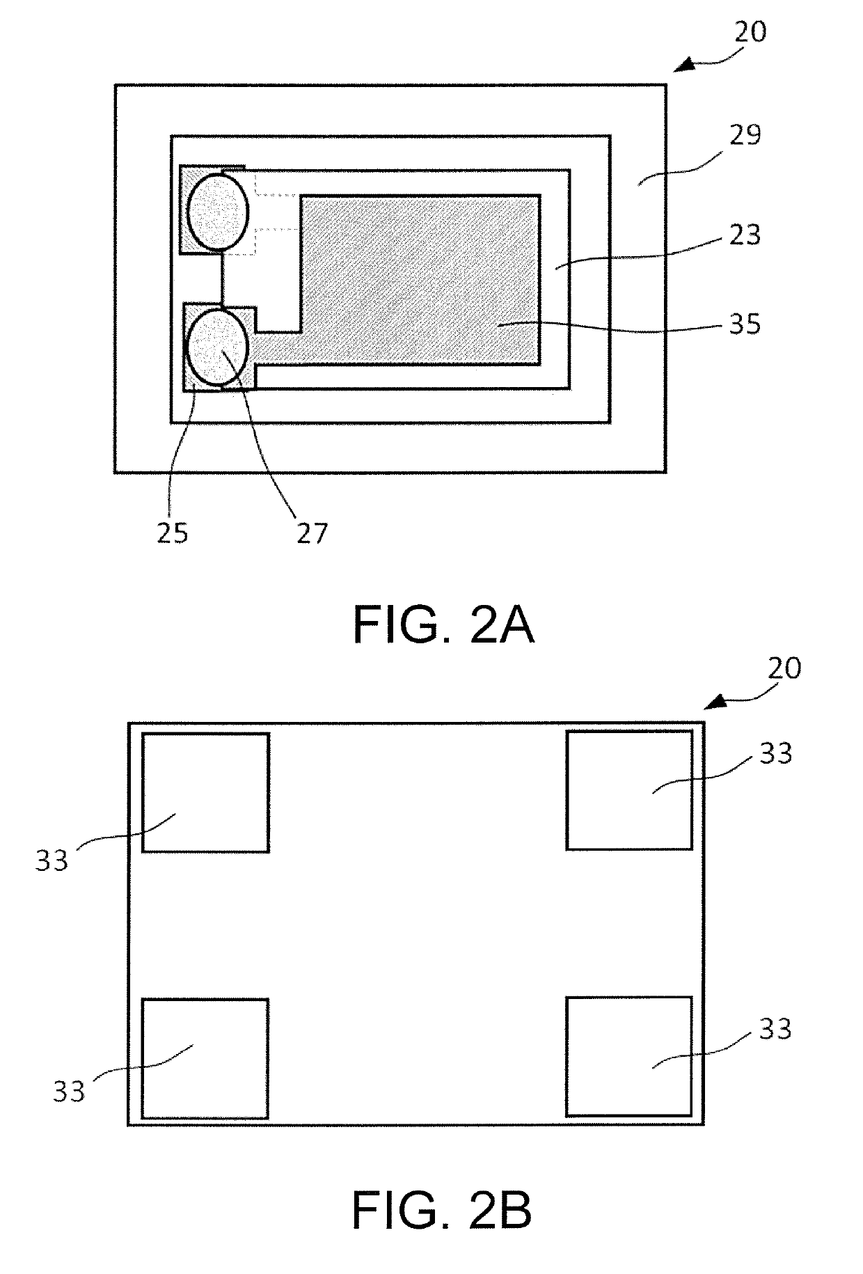
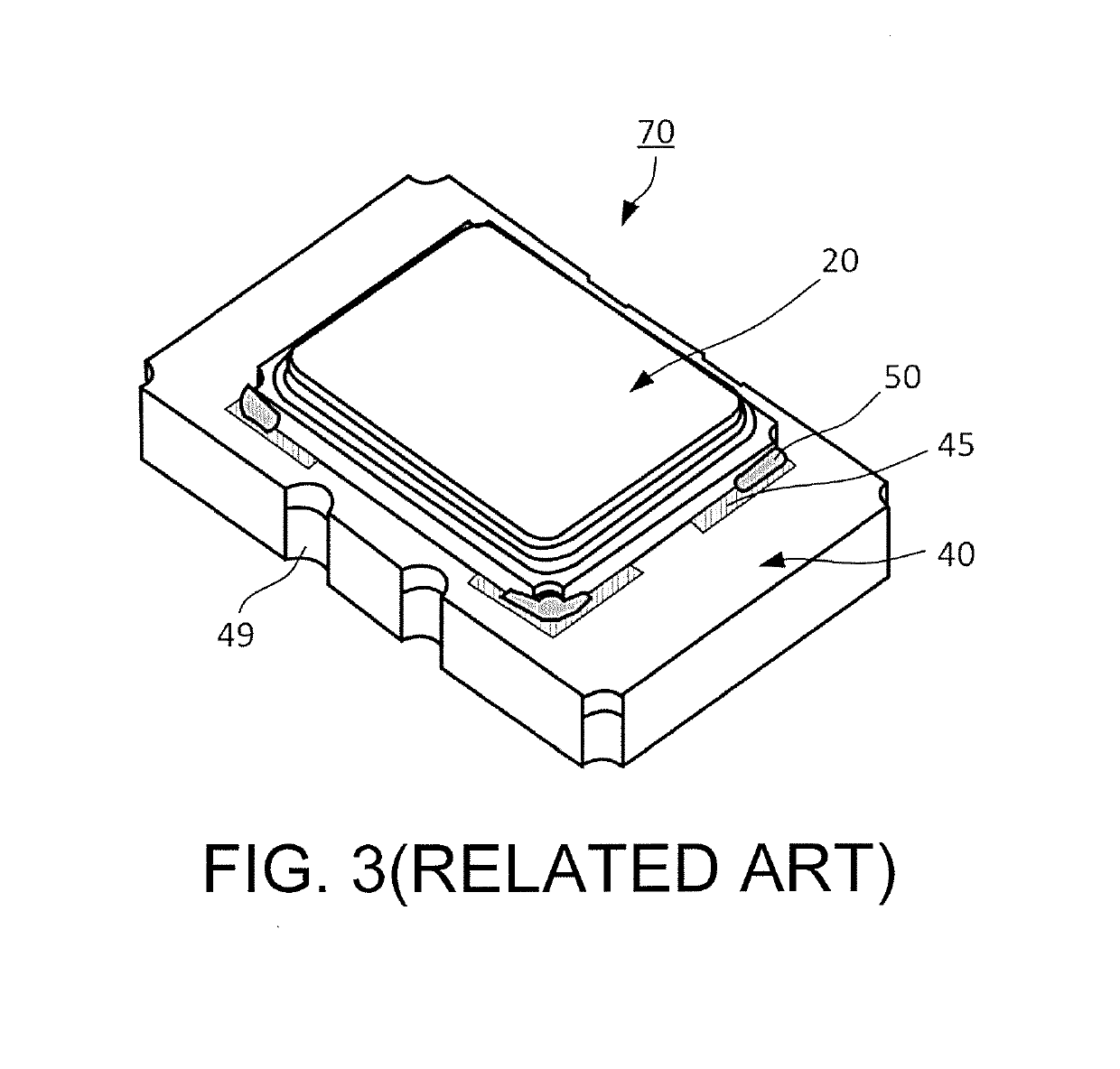
[0036]While in a conventional laminated type crystal oscillator, the mounting substrate and the surface mount type crystal unit are laminated such that both long sides are parallel to one another (see FIG. 3), the mounting substrate and the surface mount type crystal unit are laminated such that both the long sides are orthogonal to one another in this disclosure. Thus, as apparent from the above-described simulation results, the stress generated in the crystal element in the crystal unit caused by the environmental temperature change of this crystal oscillator is reduced compared with the conventional manner. Accordingly, the improvement of the hysteresis characteristics of the frequency / temperature characteristics can be expected.

Problems solved by technology

One of causes that degrade the hysteresis characteristics of the laminated type crystal oscillator is stress generated in a crystal element.

Method used


Image

  • Crystal oscillator
  • Crystal oscillator
  • Crystal oscillator

Examples


Embodiment Construction

[0015]The following describes an embodiment of a crystal oscillator according to this disclosure with reference to the drawings. Each drawing used in the description is merely illustrated schematically for understanding this disclosure. In each drawing used in the description, like reference numerals designate corresponding or identical elements, and therefore such elements may not be further elaborated here. Shapes, dimensions, materials, and a similar factor described in the following embodiment are merely preferable examples within the scope of this disclosure. Therefore, this disclosure is not limited to only the following embodiment.

[0016]1. Explanation of Structure

[0017]FIG. 1A and FIG. 1B are explanatory drawings illustrating a crystal oscillator 10 according to the embodiment. Especially, FIG. 1A is a perspective view of the crystal oscillator 10 according to the embodiment. FIG. 1B is a sectional drawing of the crystal oscillator 10 according to the embodiment and a section...


PUM


Abstract

A crystal oscillator includes a surface mount type crystal unit and a mounting substrate. The surface mount type crystal unit includes a ceramic container. The surface mount type crystal unit has a rectangular shape as a planar shape. The mounting substrate includes a ceramic substrate on which an electronic component is mounted, the mounting substrate having a rectangular shape as a planar shape. The crystal oscillator has a structure where the surface mount type crystal unit and the mounting substrate are laminated, and both terminals of the surface mount type crystal unit and the mounting substrate are connected with a bonding material. The mounting substrate and the surface mount type crystal unit are connected in a positional relationship where a long side of the mounting substrate and a long side of the surface mount type crystal unit are orthogonal.

Description

CROSS-REFERENCE TO RELATED APPLICATIONS[0001]This application is based on and claims priority under 35 U.S.C. § 119 to Japanese Patent Application No. 2016-011206, filed on Jan. 25, 2016, the entire content of which is incorporated herein by reference.TECHNICAL FIELD[0002]This disclosure relates to a surface mount type crystal oscillator having a structure where a mounting substrate on which electronic components are mounted and a surface mount type crystal unit are laminated.DESCRIPTION OF THE RELATED ART[0003]A crystal oscillator is a frequency reference source required for information-driven society. For example, there is known a surface mount type crystal oscillator (hereinafter referred to as a laminated type crystal oscillator) described in Japanese Unexamined Patent Application Publication No. 2000-353919, specifically see FIG. 1 and claim 2, as one type of such crystal oscillator. The surface mount type crystal oscillator has a structure where a mounting substrate and a surf...

Claims


Application Information

Patent Timeline
Patent Type & Authority Patents(United States)
IPC IPC(8): H03B5/32H03L7/00H03H9/10H03L1/00
CPCH03B5/32H03L7/00H03L1/00H03H9/10H03H9/08H03H9/02102H03H9/0519H03H9/0547H03H9/1014H03H9/175
Inventor WATANABE, YOSHIHIRO
Owner NIHON DEMPA KOGYO CO LTD
Learn More