Portable chest tube pressure and CO2 monitor

a chest tube and monitor technology, applied in the field of chest tubes, can solve the problems of only two-dimensional visualization, inability to definitively confirm the three-dimensional location of the chest tube, and the tendency of the lung to collapse, and achieve the effect of greater objectivity

Active Publication Date: 2019-07-02
MAYO FOUND FOR MEDICAL EDUCATION & RES
View PDF37 Cites 0 Cited by
  • Summary
  • Abstract
  • Description
  • Claims
  • Application Information

AI Technical Summary

Benefits of technology

[0014]Particular embodiments of the subject matter described in this document can be implemented to realize one or more of the following advantages. First, in some embodiments the systems and methods provided herein can be used to confirm whether a chest tube is properly placed within a patient's pleural space. In some circumstances, such systems and methods can provide more a definitive confirmation of proper chest tube placement than current methods. For example, chest radiographs are sometimes currently used in attempt to confirm the proper placement of chest tubes. However, such radiographical images typically provide only two-dimensional visualization. Therefore, a chest radiograph may not provide a definitive confirmation of the three-dimensional location of the chest tube within the patient's pleural space. Secondly, in some embodiments the systems and methods provided herein can be used to confirm proper chest tube placement with greater objectivity than some current techniques. For example, in another current technique used in attempt to confirm proper chest tube placement, a visual inspection of the passage of gas bubbles through a water-seal chest drainage unit is performed. However, such visual inspection is inherently subjective and prone to human error. In contrast, in some embodiments the systems and methods provided herein allow for objective detection and quantification of the proper placement of chest tubes by monitoring CO2 extracted from the pleural space. Further, in some embodiments the systems and methods provided herein allow for objective detection and quantification of the proper placement of chest tubes by monitoring the pressure within the chest tube. Third, in some embodiments the systems and methods provided herein can assist with a determination of whether an air leak is an internal or an external air leak.

Problems solved by technology

If air enters the pleural space, the lung will tend to collapse.
This is a weakness and out-pouching of the lung tissue, which can rupture.
However, such radiographical images typically provide only two-dimensional visualization.
Therefore, a chest radiograph may not provide a definitive confirmation of the three-dimensional location of the chest tube within the patient's pleural space.
However, such visual inspection is inherently subjective and prone to human error.

Method used


Image

  • Portable chest tube pressure and CO<sub>2 </sub>monitor
  • Portable chest tube pressure and CO<sub>2 </sub>monitor

Examples


Embodiment Construction

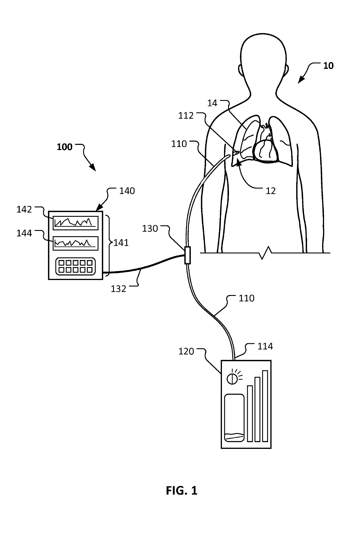
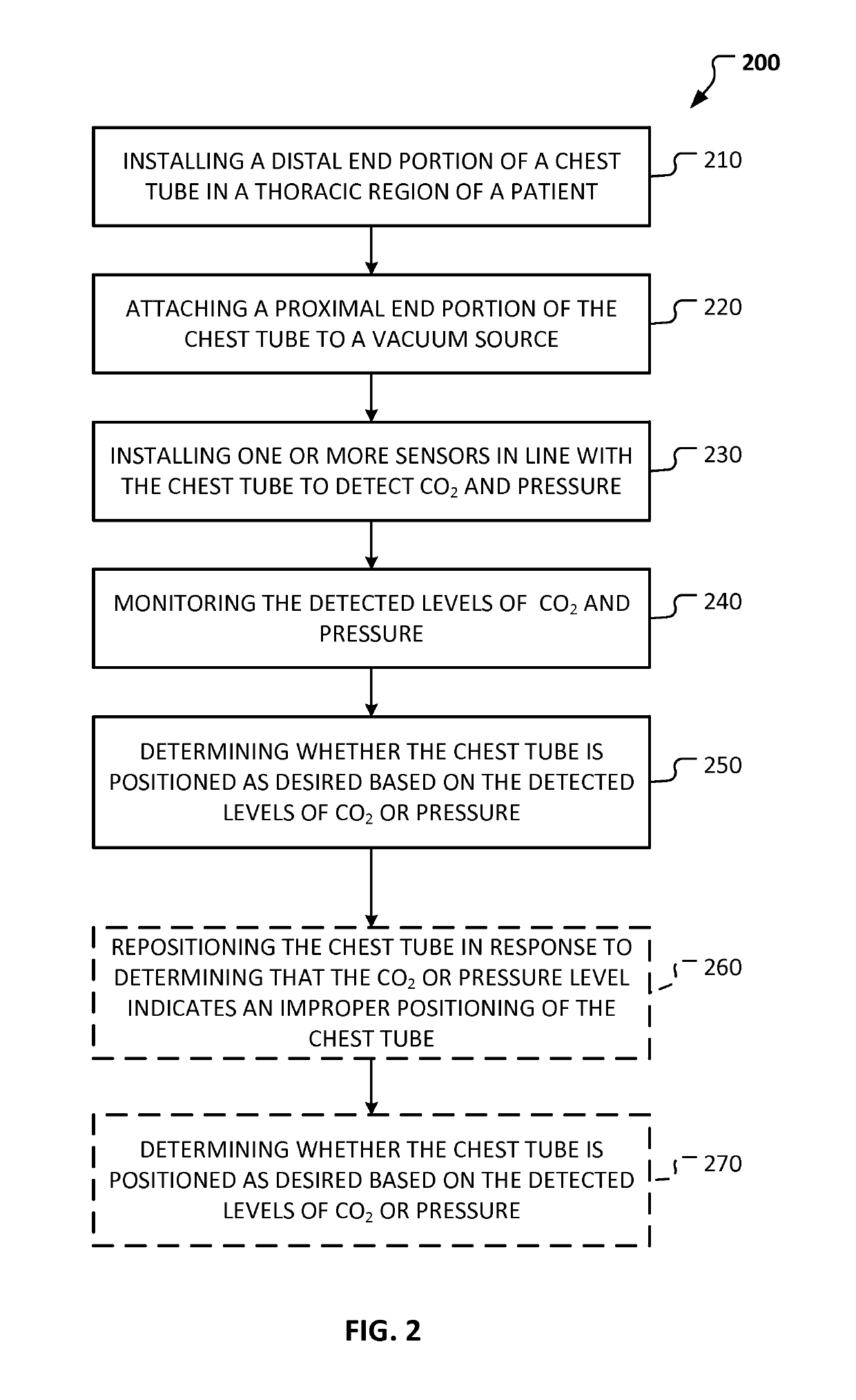
[0020]This document provides systems and methods that can improve the efficacy of tube thoracostomy. For example, this document provides devices and methods for confirming the proper placement of a chest tube within the pleural space.

[0021]Pneumothorax (air in the pleural space) can be life-threatening. The immediate treatment for pneumothorax is tube thoracostomy, or the insertion of a chest tube. A long, flexible, hollow, narrow tube is inserted through the ribs into the pleural space, and the tube is attached to a suction device. This allows the air to be evacuated from the pleural space, and allows the lung to re-expand. Chest tubes are generally inserted using local anesthesia. The chest tube is left in place until the lung leak seals on its own, which usually occurs within two to five days.

[0022]Some pneumothorax conditions can be characterized by the presence of CO2 in the air within the pleural space. For example, when a lung is punctured, some of the air that is exhaled fro...


PUM


Abstract

Systems and methods can be used improve the efficacy of tube thoracostomy. For example, this document provides devices and methods for confirming the proper placement of a chest tube within the pleural space.

Description

CROSS REFERENCE TO RELATED APPLICATIONS[0001]This application is a National Stage application under 35 U.S.C. § 371 of International Application No. PCT / US2015 / 010414, having an International Filing Date of Jan. 7, 2015, which claims the benefit of U.S. Provisional Application No. 61 / 924,336, file Jan. 7, 2014. The disclosure of the prior application is considered part of and is incorporated by reference in the disclosure of this application.BACKGROUND[0002]1. Technical Field[0003]This document relates to systems and methods that can improve the efficacy of chest tube thoracostomy. For example, this document relates to devices and methods for confirming the proper placement of a chest tube within the pleural space.[0004]2. Background Information[0005]The lungs are paired organs that lie in the thoracic cavity. A gas transfer takes place in the lungs, with oxygen from inhaled air being transported into the blood, and carbon dioxide (CO2) being removed from the blood. The CO2 is then ...

Claims


Application Information

Patent Timeline
Patent Type & Authority Patents(United States)
IPC IPC(8): A61M1/04A61B5/00A61B5/083A61M1/00
CPCA61M1/04A61B5/0086A61B5/0836A61M1/0074A61M2230/432A61M2205/3303A61M2205/3313A61M2205/3331A61M2205/502A61M2205/18A61M1/802
Inventor AHO, JOHNATHON M.RUPAREL, RAAJ K.ROWSE, PHILLIP G.
Owner MAYO FOUND FOR MEDICAL EDUCATION & RES
Why Eureka
Try Eureka