Reduction of LED headlight flickering in electronic mirror applications

a technology of electronic mirrors and led headlights, applied in the field of video capture devices, can solve the problems of flickering, no standardized led cycle frequency, no current industry standard for the frequency or duty cycle of pulsing for leds, etc., and achieve the effect of reducing led headlight flickering

Active Publication Date: 2019-07-02
AMBARELLA INT LP
View PDF12 Cites 0 Cited by
  • Summary
  • Abstract
  • Description
  • Claims
  • Application Information

AI Technical Summary

Benefits of technology

[0007]The objects, features and advantages of the present invention include providing a reduction of LED headlight flickering in electronic mirror applications that may (i) analyze video images for pulsed light sources, (ii) leaving pixels unmodified for a subset of objects based on a criteria indicating that the subset of objects is known to be intentionally flickering, (iii) classify detected objects, (iv) mask flickering in a processor domain, (v) mask flickering in a sensor domain, (vi) mask flickering at a display device, (vii) display a version of the captured video signal with modified pixels, (viii) determine average values over consecutive frames, (ix) modify a gain of a group of pixels on a frame-by-frame basis, (x) increase a shortest exposure for a group of pixels and / or (xi) be easy to implement.

Problems solved by technology

However, there is no standardized LED cycle frequency.
In current electronic display applications there may be a problem with flickering when displaying images of light sources.
Furthermore, there is no current industry standard for the frequency or duty cycle of pulsing for LEDs.
Therefore, designing an electronic display capable of handling a specific frequency or duty cycle is impractical.

Method used


Image

  • Reduction of LED headlight flickering in electronic mirror applications
  • Reduction of LED headlight flickering in electronic mirror applications
  • Reduction of LED headlight flickering in electronic mirror applications

Examples


Embodiment Construction

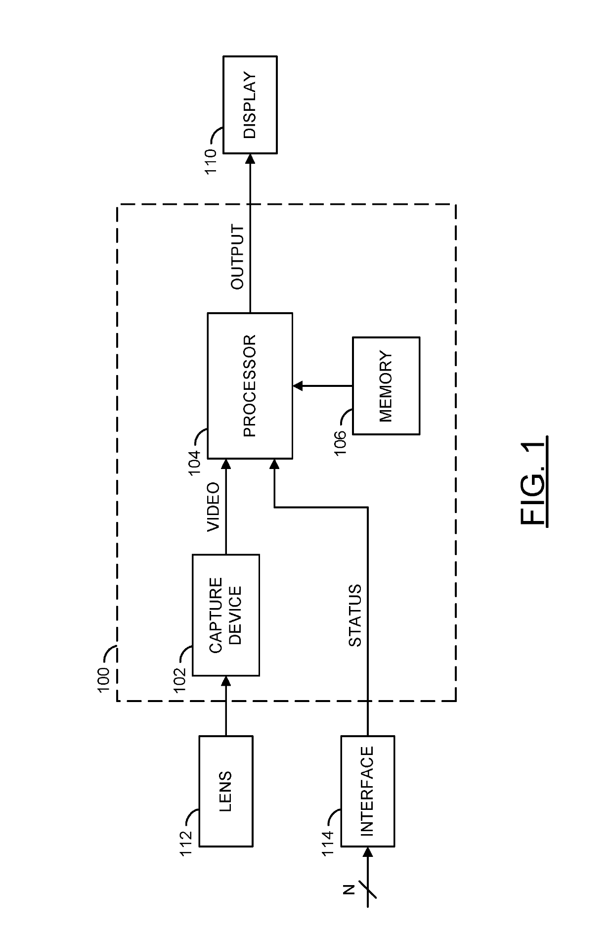
[0018]Referring to FIG. 1, a block diagram of an apparatus 100 is shown in accordance with an embodiment of the present invention. The apparatus 100 may be a camera system. The camera system 100 may comprise a block (or circuit) 102, a block (or circuit) 104, and / or a block (or circuit) 106. The circuit 102 may be configured as a capture device. The circuit 104 may be configured as a processor. The circuit 106 may be configured as a memory. The camera system 100 is shown connected to a block (or circuit) 110. The circuit 110 may be a display device. In some embodiments, the display device 110 may be implemented as part of the camera system 100. The display device 110 may be implemented as an electronic mirror (e.g., a rearview mirror and / or a sideview mirror). In some embodiments, multiple display devices 110 may be implemented.

[0019]The camera system 100 is shown receiving input from a block (or circuit) 112. The block 112 may be a lens (e.g., a camera lens). In some embodiments, t...


PUM


Abstract

An apparatus includes a sensor and a processor. The sensor may be configured to generate a first video signal. The processor may be configured to search for a flickering effect in a frame of the first video signal, determine a location and a region of pixels to modify within the frame in response to the flickering effect, determine a modification based on the flickering effect, perform the modification of the region of pixels by determining average values of pixels based on the location of the region of pixels over consecutive frames of the first video signal and generate a second video signal in response to the modification of the region of pixels and the first video signal. The second video signal may present a modified version of the region of pixels to mask the flickering effect when viewing the second video signal on a display.

Description

[0001]This application relates to U.S. Ser. No. 14 / 729,332, filed Jun. 3, 2015, which is incorporated by reference in its entirety.FIELD OF THE INVENTION[0002]The present invention relates to video capture devices generally and, more particularly, to a reduction of LED headlight flickering in electronic mirror applications.BACKGROUND OF THE INVENTION[0003]For certain light sources, such as LED or Fluorescent sources, the peak brightness is fixed and cannot be modulated. Manufacturers of light sources with fixed brightness dim the brightness of the light source by shortening the duty cycle. The duty cycle of the light source is kept on for a part of the cycle, and off for the rest of the cycle. A typical LED cycle frequency is in the 300-700 Hz range. However, there is no standardized LED cycle frequency.[0004]In current electronic display applications there may be a problem with flickering when displaying images of light sources. LED light sources are pulsed to turn on and off many ...

Claims


Application Information

Patent Timeline
Patent Type & Authority Patents(United States)
IPC IPC(8): B60R1/00G06K9/20G06K9/00G06V10/22
CPCG06K9/2027G06K9/00825B60R1/005B60R1/00B60R2300/30G06V20/584G06V10/22
Inventor PERTSEL, SHIMONDAY, CHRISTOPHER N.FINK, ALEXANDER
Owner AMBARELLA INT LP
Why Eureka
Try Eureka