Shear resistant bin level indicator

a bin level indicator and resistance technology, applied in the field of indicators, can solve the problems of affecting the accuracy of the over-travel section, being vulnerable to shear damage, etc., and achieve the effect of short exposure and immunity to shear force damag

Active Publication Date: 2009-08-25
HENDERSON EDWIN LEE
View PDF7 Cites 4 Cited by
  • Summary
  • Abstract
  • Description
  • Claims
  • Application Information

AI Technical Summary

Benefits of technology

[0012](c) to provide a level indicator that is less sensitive to the effect of the material stream entering the bin and impinging on the paddle.
[0017]Various embodiments of the present invention utilize a paddle which may be comprised of a single rod or any suitable shape that will fit through the mounting hole. The paddle is attached to a paddle shaft. The paddle shaft has a relatively short exposure after leaving the housing and entering the bin. This short distance protects the paddle shaft from excessive bending forces, making it immune to shear force damage caused by the weight of the material in the bin. In various embodiments of the present invention, the paddle is connected at a point below the paddle shaft with a center line along its length that is approximately 60 degrees in relation to the paddle shaft and approximately 30 degrees in relation to the bin wall. The paddle is therefore pointed down into the container at an angle.
[0018]Between the paddle and the paddle shaft is an over-travel mechanism, which may be of any design that allows the paddle to move without damage at the urging of the bulk material. A somewhat similar over-travel mechanism can be seen in the prior art, Gruber U.S. Pat. No. 3,542,982 (1970). However, as applied in prior art, the flexible section is in line with the axis of the paddle shaft making it very vulnerable to shear damage. In a disclosed embodiment of the present invention, the flexible section is in line with the center line of the length of the paddle, and not in line with the axis of the shaft. This allows the paddle to be forced to an approximately vertical position at an angle of approximately 90 degrees in relation to the paddle shaft, as would be the case with material moving down in the bin. The paddle would then be aligned more or less parallel to the movement of the material in the bin. The material will slide past the paddle without doing any damage to the paddle, the over-travel section, or the paddle shaft. Once the material is no longer in contact with the paddle, the flexible section will allow the paddle to spring back to its normal relationship to the bin wall. In various embodiments of the present invention, this position of the paddle allows the paddle to reach out and thoroughly engage the material. If this same over-travel and paddle arrangement were applied to a common rotary indicator, the over-travel section itself would be damaged when bent at a 90 degree angle or greater by the large forces of the heavy material. The bending would be greatest when, during the 360 degree rotation of the shaft, the paddle is pointing up, at a 12 o'clock position.
[0020]The paddle may be made relatively long, resulting in increased leverage and in turn providing greater sensitivity to low density material. At the same time the paddle may be inserted into the bin through a relatively small opening in the side of the storage bin or container. This opportunity cannot practically be duplicated with a continuously rotating shaft. In various embodiments of the present invention, the paddle is relatively immune to stringy material hanging on the paddle. Such material will tend to slide off of the paddle.

Problems solved by technology

However, as applied in prior art, the flexible section is in line with the axis of the paddle shaft making it very vulnerable to shear damage.
If this same over-travel and paddle arrangement were applied to a common rotary indicator, the over-travel section itself would be damaged when bent at a 90 degree angle or greater by the large forces of the heavy material.

Method used


Image

  • Shear resistant bin level indicator
  • Shear resistant bin level indicator
  • Shear resistant bin level indicator

Examples


Embodiment Construction

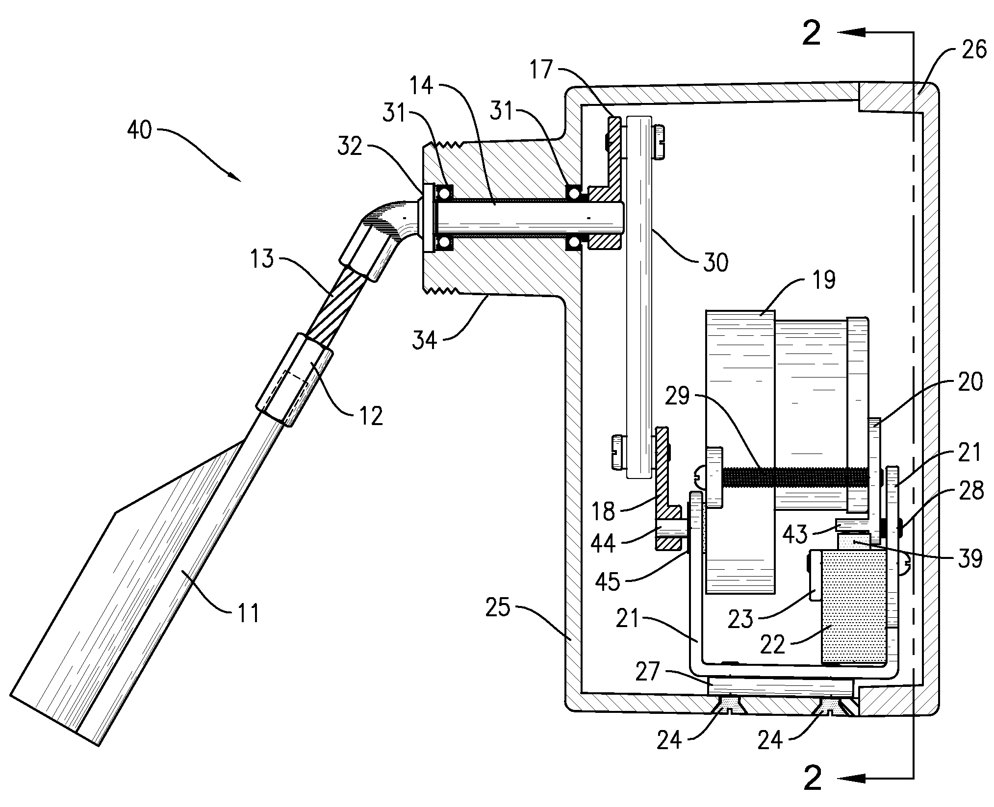
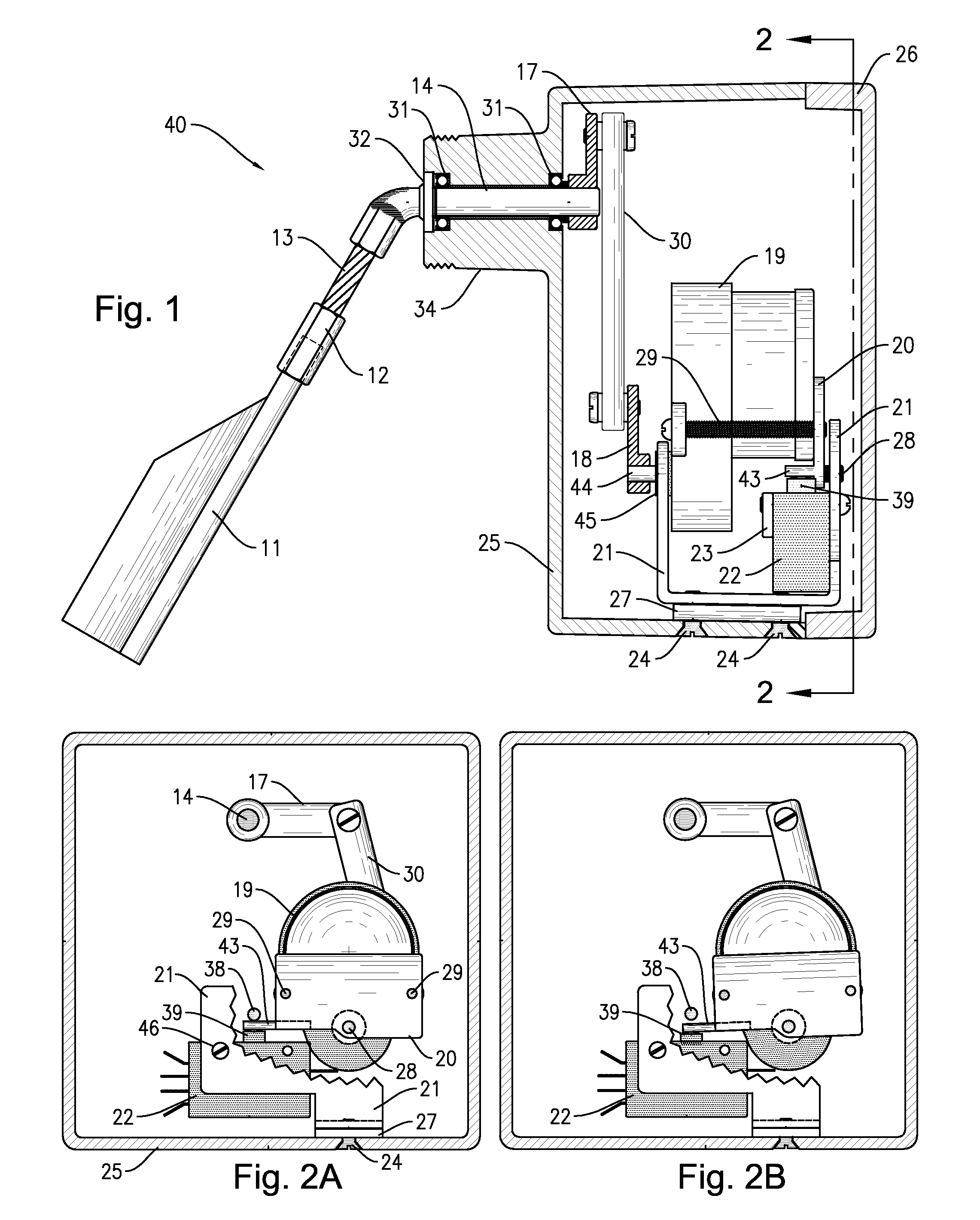
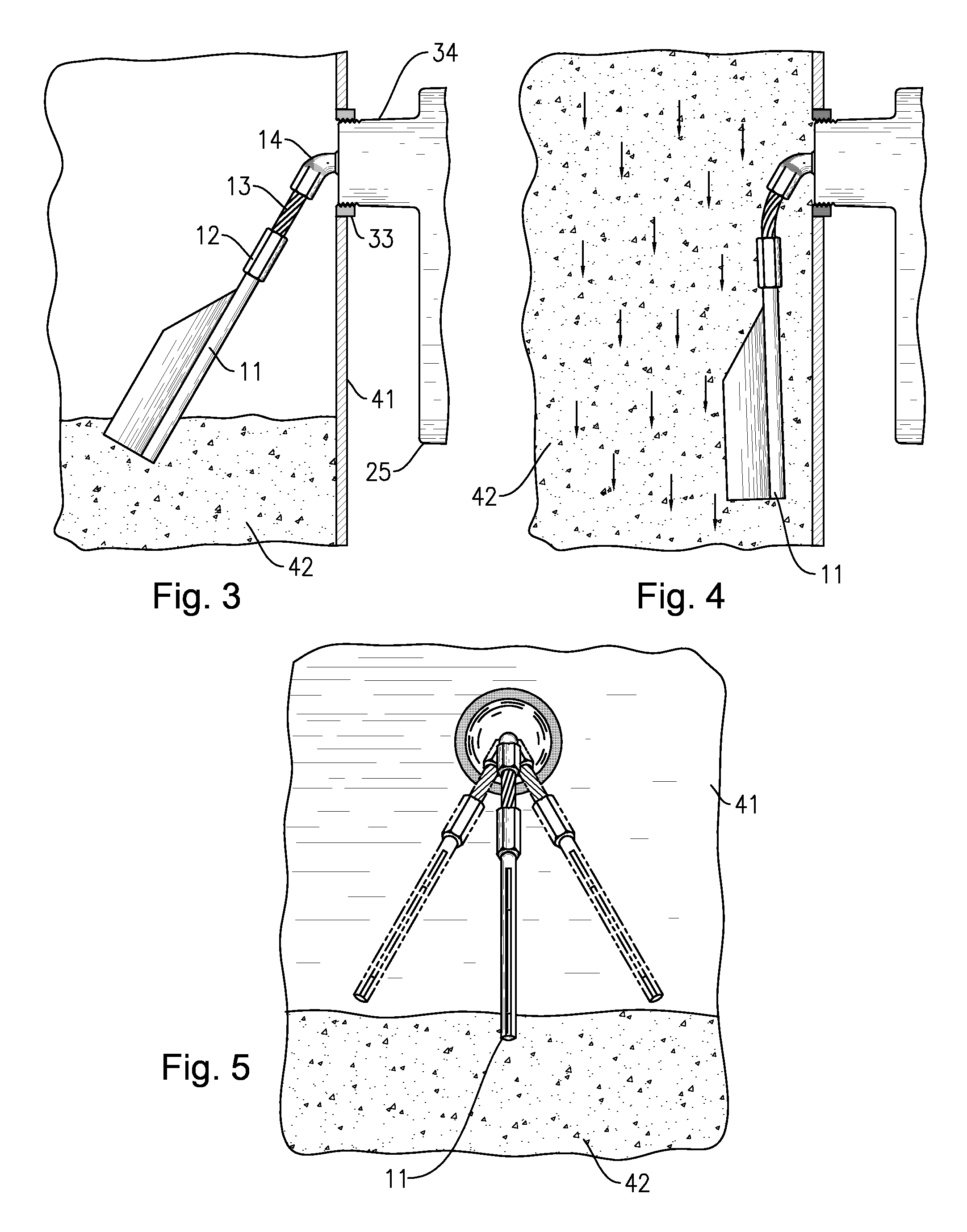
[0028]For purposes of illustration, a preferred embodiment of the present invention has been depicted as a bin level indicator 40 incorporating a hollow housing body 25 and a housing cover 26. The housing 25 includes a mounting stem 34 which engages a mounting gland 33 that is attached to a bin wall 41. Various methods such as bayonet, clamp, or set screw may be used to attach the housing to bins, silos, hoppers, chutes, or storage vessels. In FIG. 3, components within the housing 25 rotate a shaft 14 in an oscillating or rocking motion. The shaft 14 extends outside the housing 25 and attached to it, is a flexible section 13 and a flexible section fitting 12. This over-travel mechanism allows the paddle 11 to move at the urging of a bulk material 42 contained within the bin and may be constructed with various active components such as a wire rope, helical coil, or spring. Attached to the fitting 12 is a paddle 11 which is designed to contact a material 42 in the storage bin. In vari...


PUM


Abstract

A device for indicating a level of a bulk material in a bin. A motor imparts a swinging motion to a paddle located inside the bin. When the paddle engages the material, drag on the paddle causes a counteracting force on the motor, indicating a presence of material at the location of the device. In various embodiments, a paddle shaft, having very little exposure inside the bin, extends from a protective enclosure. The shaft is capped with a flexible section having the paddle attached to it. The paddle is at a downward angle relative to the paddle shaft and extends into the bin so as to engage the material. The paddle may move at an urging of the material so as to avoid damage to the paddle, flexible section, and shaft.

Description

CROSS-REFERENCE TO RELATED APPLICATIONS[0001]This is a continuation in part of application Ser. No. 11 / 551,705, filed Oct. 21, 2006, now abandoned.BACKGROUND OF THE INVENTION[0002](1) Field of the Invention[0003]This invention relates in general to indicators, and more particularly relates to indicators of the level of dry bulk materials within storage bins, silos, hoppers, containment structures or storage tanks.[0004](2) Description of the Related Art[0005]Bin level indicators are used to sense the presence or absence of granular material within a bulk material container. The contents of these bins and containers vary greatly and may include virtually any type of bulk material from wood chips to grain to fertilizer to calcium dust. Many variations in the operating conditions of a level indicator have led to the creation of many different types of indicators with various applications and uses. The common goal of these devices is to convey an accurate indication of the level of mate...

Claims


Application Information

Patent Timeline
Patent Type & Authority Patents(United States)
IPC IPC(8): H01H35/00
CPCG01L5/26G01L5/00
Inventor HENDERSON, EDWIN LEE
Owner HENDERSON EDWIN LEE
Why Eureka
Try Eureka