Airbag apparatus

a technology of airbags and apparatuses, which is applied in the directions of pedestrian/occupant safety arrangements, vehicular safety arrangements, vehicle components, etc., can solve the problems of low workability of mounting curtain airbag apparatuses and the possibility of vehicle body panels dropping curtain airbag apparatuses off, so as to improve the workability of temporary fixation and perform more easily

Active Publication Date: 2019-07-02
HONDA MOTOR CO LTD
View PDF22 Cites 0 Cited by
  • Summary
  • Abstract
  • Description
  • Claims
  • Application Information

AI Technical Summary

Benefits of technology

[0007]However, the temporary fixing claw is just locked in the locking hole while the curtain airbag apparatus is temporarily fixed. The curtain airbag apparatus is likely to drop off the vehicle body panel during temporary fixation work. For this reason, there is the problem of low workability of the work of mounting the curtain airbag apparatus. For example, since the cover is not in contact with a lower surface of a bent portion formed at the vehicle body panel in Japanese Patent No. 5180554, the cover is also not in contact with the lower surface of the bent portion while the curtain airbag apparatus is temporarily fixed. If the cover is not in contact with the lower surface of the bent portion of the vehicle body panel, as described above, the curtain airbag apparatus can move upward easily with respect to the vehicle body panel while the curtain airbag apparatus is temporarily fixed. Thus, the curtain airbag apparatus may drop off easily in, for example, a case where a worker touches the curtain airbag apparatus. Since the temporary fixing claw is just locked due to the weight of the curtain airbag apparatus, as described above, the curtain airbag apparatus is likely to drop off the vehicle body panel especially if the curtain airbag apparatus is moved upward.
[0023]According to the present disclosure, the work of locking the temporary fixing claw of the piece of fixing hardware into the locking portion of the vehicle body panel can be performed more easily than in a case where the contact portion is present on two sides of the piece of fixing hardware. It is thus possible to improve the workability of temporary fixation.

Problems solved by technology

For this reason, there is the problem of low workability of the work of mounting the curtain airbag apparatus.
Since the temporary fixing claw is just locked due to the weight of the curtain airbag apparatus, as described above, the curtain airbag apparatus is likely to drop off the vehicle body panel especially if the curtain airbag apparatus is moved upward.

Method used


Image

  • Airbag apparatus
  • Airbag apparatus
  • Airbag apparatus

Examples


Embodiment Construction

[0028]One embodiment of an airbag apparatus according to the present disclosure will be described below with reference to the drawings. Note that each member is appropriately rescaled to a recognizable size in the drawings below.

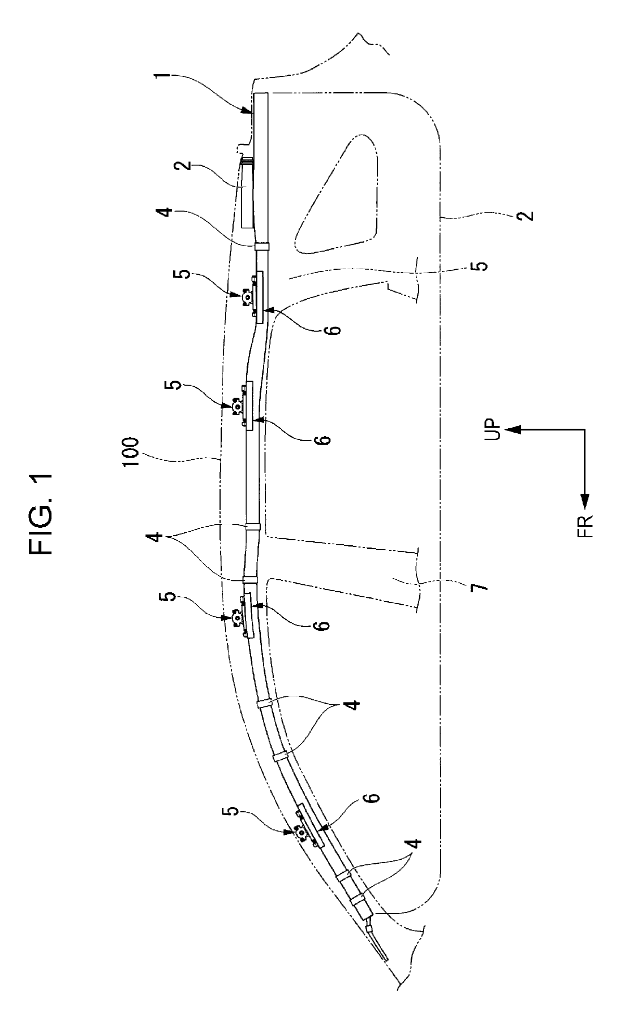
[0029]FIG. 1 is a front view showing a side curtain airbag apparatus 1 (an airbag apparatus) according to the present embodiment and part of a vehicle body panel 100, to which the side curtain airbag apparatus 1 is fixed. Note that FIG. 1 is a view as viewed from a vehicle inner side and a vehicle width direction of a vehicle, on which the side curtain airbag apparatus 1 according to the present embodiment is mounted. That is, a leftward direction indicated by an arrow FR is toward a vehicle front side while an upward direction indicated by an arrow UP is toward a vehicle upper side, as shown in FIG. 1.

[0030]As shown in FIG. 1, the side curtain airbag apparatus 1 according to the present embodiment includes an inflator2, a bag 3, binding bands 4, pieces 5 of...


PUM


Abstract

There is provided a side curtain airbag apparatus. The side curtain airbag apparatus includes a bag that is inflated and unfolded, a piece of fixing hardware that is fixed to an edge portion of the bag and includes a temporary fixing claw capable of being locked to a locking portion of a vehicle body panel, and a protector that includes a lower contact portion in contact with a lower surface of a bent portion of the vehicle body panel and surrounds the bag.

Description

CROSS REFERENCES TO RELATED APPLICATIONS[0001]The present application claims priority under 35 U.S.C. § 119 to Japanese Patent Application No. 2015-155371, filed Aug. 5, 2015, entitled “Airbag Apparatus.” The contents of this application are incorporated herein by reference in their entirety.BACKGROUND[0002]1. Field[0003]The present disclosure relates to an airbag apparatus.[0004]2. Description of the Related Art[0005]For example, a so-called curtain airbag apparatus may be installed as an airbag apparatus at a roof side portion of a vehicle body, as described in Japanese Patent No. 5180554. A curtain airbag apparatus disclosed in Japanese Patent No. 5180554 includes a bag which is inflated and unfolded at the time of a collision, fixing hardware which fixes the bag to a vehicle body panel, and a cover which surrounds the bag so as to protect the bag.SUMMARY[0006]When the curtain airbag apparatus in Japanese Patent No. 5180554 is to be assembled to a vehicle body, the curtain airbag...

Claims


Application Information

Patent Timeline
Patent Type & Authority Patents(United States)
IPC IPC(8): B60R21/213B60R11/00
CPCB60R21/213B60R2011/0059
Inventor TAKAHASHI, KEITONOKA, DAIEI
Owner HONDA MOTOR CO LTD
Why Eureka
Try Eureka