Portable working machine

a working machine and portable technology, applied in the direction of metal-working machine components, manufacturing tools, working accessories, etc., can solve the problems of deformation of the stopper, the inability to prevent the rotation of the wheel guard by the stopper, and the inability to fulfill the role of the wheel guard, so as to reduce the workability of the portable working machine, the strength of the wheel guard per se is increased, and the weight of the wheel guard is increased.

Active Publication Date: 2014-11-04
KOKI HLDG CO LTD
View PDF5 Cites 0 Cited by
  • Summary
  • Abstract
  • Description
  • Claims
  • Application Information

AI Technical Summary

Benefits of technology

[0006]On the other hand, it is also conceivable to firmly manufacture the wheel guard with a material such as iron in order to solve the above-described problem. However, in that case, the weight of the wheel guard is increased and may lower the workability of the portable working machine. Moreover, although the strength of the wheel guard per se is increased by changing the material, the effect of preventing rotation of the wheel guard by the stopper remains insufficient, and thus it has been necessary to improve the strength the rotation preventing mechanism per se.

Problems solved by technology

Even when breakage is prevented by increasing the strength of the wheel guard, if a piece of damaged wheel collides with the wheel guard and the shock of the collision is directly applied to a stopper and it causes breakage or plastic deformation of the stopper, the role of the wheel guard is not fulfilled.
Furthermore, if, for example, when the wheel guard rises over the stopper upon breakage of the blade and rotates by more than its predetermined pivoting angle, rotation of the wheel guard cannot be prevented by the stopper.
However, in that case, the weight of the wheel guard is increased and may lower the workability of the portable working machine.
Moreover, although the strength of the wheel guard per se is increased by changing the material, the effect of preventing rotation of the wheel guard by the stopper remains insufficient, and thus it has been necessary to improve the strength the rotation preventing mechanism per se.

Method used


Image

  • Portable working machine
  • Portable working machine
  • Portable working machine

Examples


first embodiment

[0021][First Embodiment]

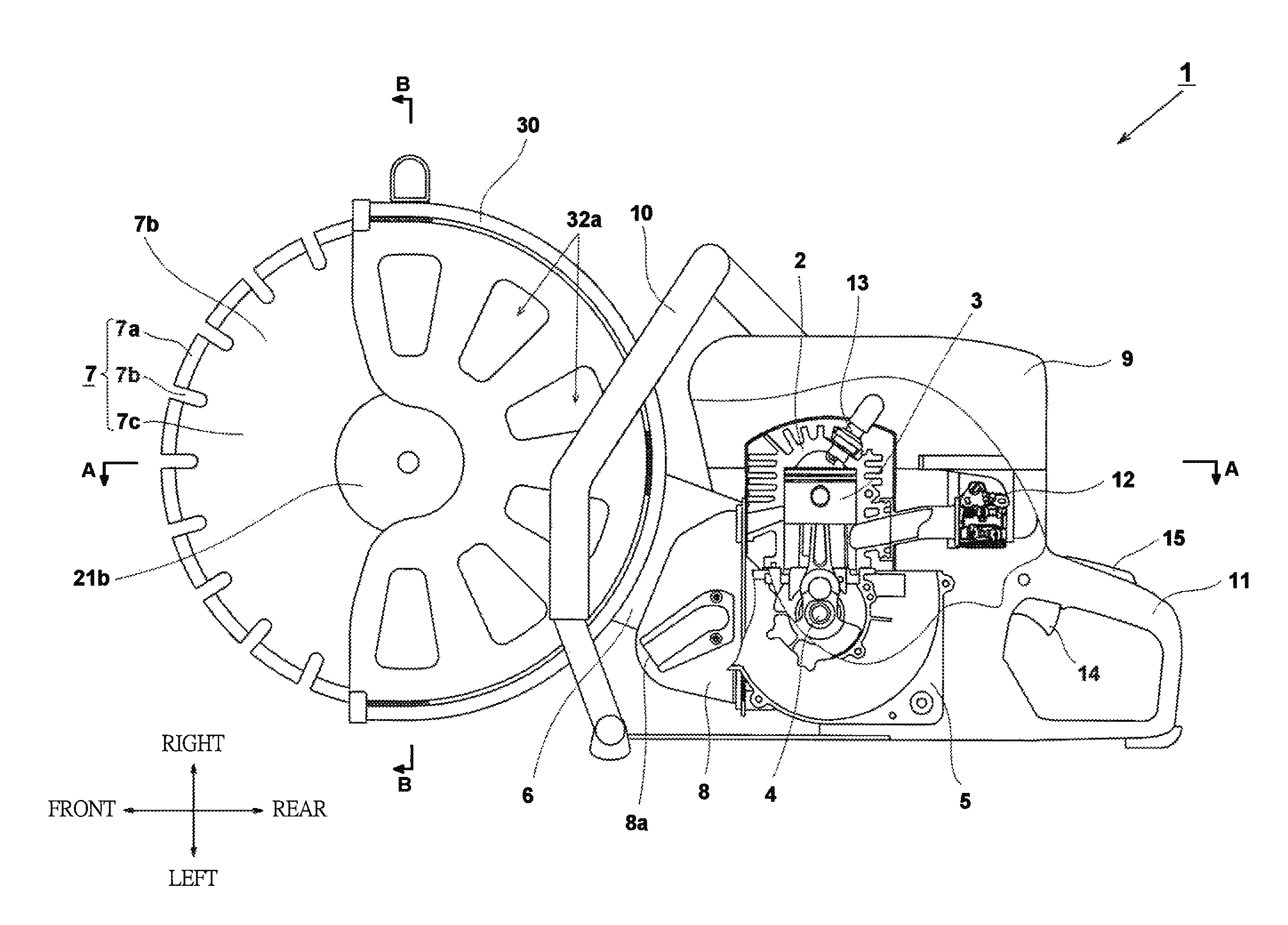
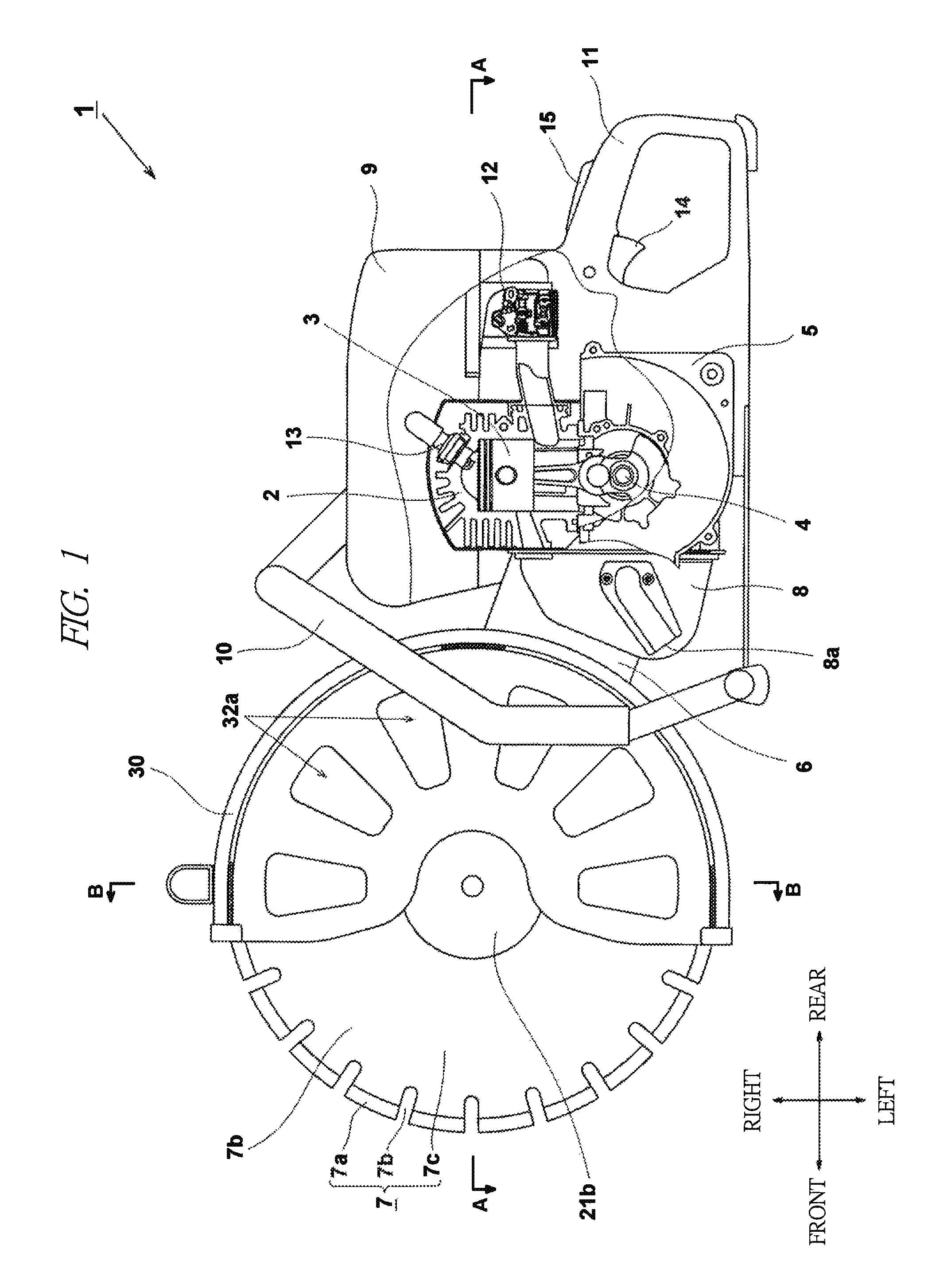
[0022]Hereinafter, embodiments of the present invention will be described based on the drawings. In the present embodiment, an engine cutter as an example of a portable working machine having a rotating tool will be described. In the drawings hereinafter, the same parts are denoted by the same reference numerals, and repeated explanations thereof will be omitted. In the present specification, the front-back, left-right, and top-bottom directions are explained on the assumption that they are those shown in the drawings.

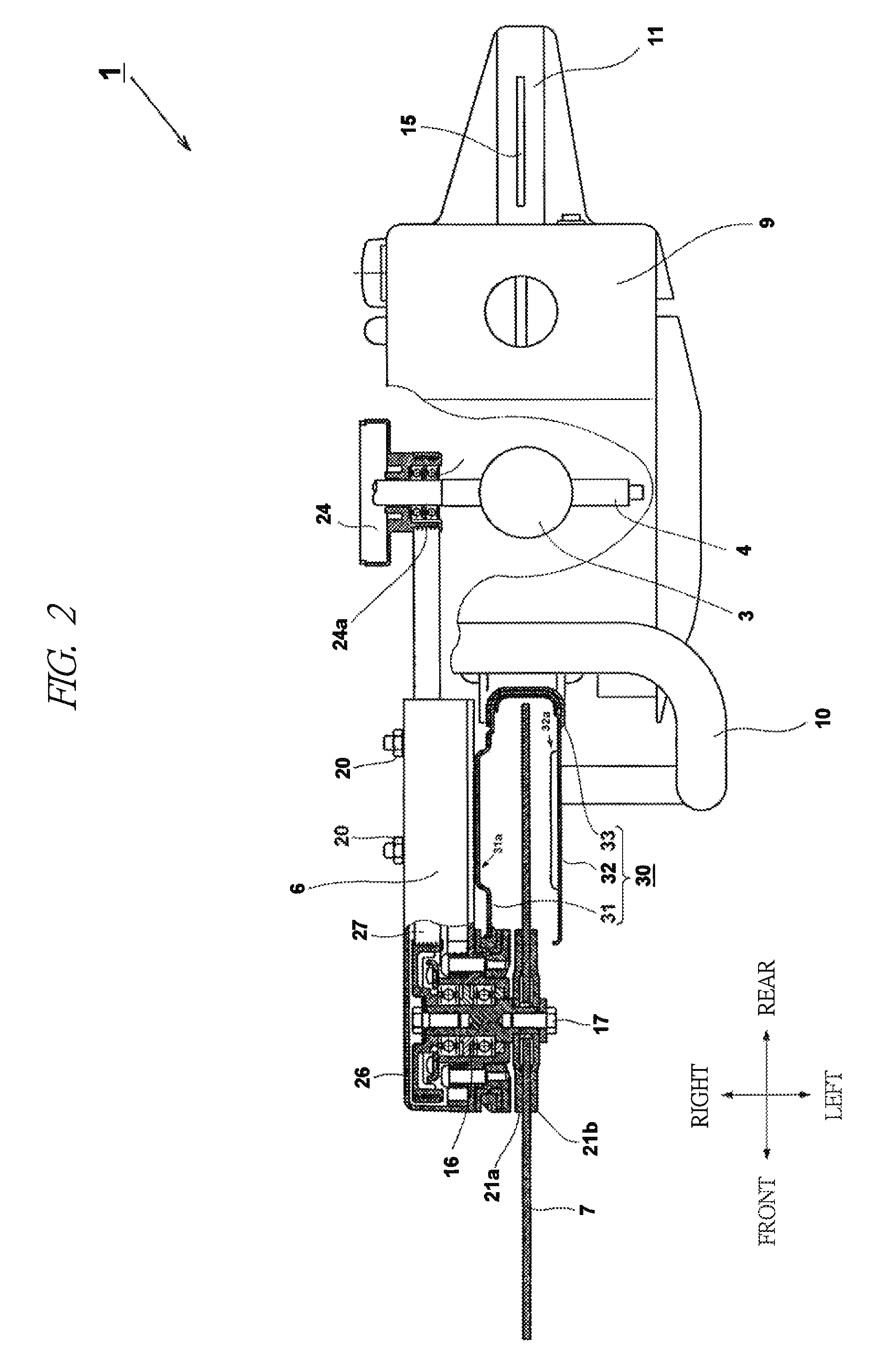
[0023]An engine cutter 1 is a working machine, which rotates a blade 7 serving as a distal-end tool by using the power from, for example, two-stroke or four-stroke engine (drive source). In the front side of the engine cutter 1, the blade (wheel) 7 of a rotating type is provided; and, in the rear side of the engine cutter 1, the engine serving as a drive source is provided. A rotating shaft (spindle, which will be described later) of the blade 7...

second embodiment

[0043][Second Embodiment]

[0044]Next, a second embodiment of the present invention will be explained with reference to FIG. 8. In a wheel guard 60 according to the second embodiment, a right-side plate 61 and a flange 64 composing the wheel guard 60 according to the second embodiment are fixed by bolts 69a and two pieces of nut 69b instead of welding. Therefore, the right-side plate 61 and the flange 64 can be formed of mutually different materials. For example, the flange 64 can be manufactured by an iron-based metal and the right-side plate 61 can be manufactured by a light metal such as an aluminum alloy, resin, and so forth. For example, In this case, the wheel guard 60 can be lighter with maintaining strength of the flange. Moreover, by fixing the right-side plate 61 and the flange 64 with the bolts, the common flange 64 or rubber damper can be utilized even when the wheel guards 60 having various sizes are prepared for blades having different diameters; therefore, cost can be r...


PUM

PropertyMeasurementUnit
degree of freedomaaaaaaaaaa
poweraaaaaaaaaa
rotation angleaaaaaaaaaa

Abstract

A portable working machine is provided with a wheel guard partially covering a wheel rotated by a drive source such as an engine, and the wheel guard is retained by a retaining portion of an arm via rubber dampers serving as elastic members. Concave-convex portions are formed on the rubber dampers, a convex-concave portion corresponding to the concave-convex portions is formed in the wheel guard side, and the wheel guard is retained by the arm so that the concave-convex portions are engaged with the convex-concave portion.

Description

CROSS-REFERENCE TO RELATED APPLICATION[0001]The present application claims priority from Japanese Patent Application No. 2011-102557 filed on Apr. 29, 2011, the content of which is hereby incorporated by reference into this application.TECHNICAL FIELD OF THE INVENTION[0002]The present invention relates to the structure of a portable working machine and particularly relates to a portable working machine having a wheel guard which guards a wheel serving as a rotating-type distal-end tool.BACKGROUND OF THE INVENTION[0003]In a portable working machine represented by an engine cutter, a wheel guard is provided so that scattering of cut powder to the surrounding area is prevented during a grinding operation. For working machines to which a wheel guard is provided, it is required to prevent a situation in which the wheel guard is rotated and displaced when a part (piece) of the wheel guard that is damaged during the grinding operation collides with the wheel guard.[0004]Therefore, to preve...

Claims


Application Information

Patent Timeline
Patent Type & Authority Patents(United States)
IPC IPC(8): B28D7/00B23Q11/06B24B55/04
CPCB28D7/00B23Q11/06
Inventor MURAKAMI, TAKUHIRO
Owner KOKI HLDG CO LTD
Why Eureka
Try Eureka