
Method of manufacturing a fuel cell module

a technology of fuel cell module and manufacturing method, which is applied in the manufacture of final products, fuel cell details, electrochemical generators, etc., can solve the problems of low workability and the inability of the cell monitor connector to be inserted into the notch, and achieve the effect of improving the workability of the cell monitor connector and low workability

Active Publication Date: 2020-07-28
TOYOTA JIDOSHA KK
View PDF4 Cites 0 Cited by
  • Summary
  • Abstract
  • Description
  • Claims
  • Application Information

AI Technical Summary

Benefits of technology

[0004]In the technique in the related art, if the positioning is displaced toward either one of the walls, the cell monitor connector and the either one of the walls interfere with each other, so that the cell monitor connector cannot be inserted into the notch. On this account, it is necessary for an operator to position the cell monitor connector by taking the measure of a positional relationship between the cell monitor connector and the walls, and thus, workability is low. In view of this, an object of this disclosure is to improve workability of attachment of a cell monitor connector.
[0005]A first aspect of the disclosure relates to an attachment method for attaching a cell monitor connector to a first separator included in a cell of a fuel cell, the cell monitor connector including a housing and a connection terminal accommodated in the housing, the cell monitor connector being electrically connected to the cell of the fuel cell. The cell includes a second separator, and a frame-shaped insulating sheet sandwiched between the first separator and the second separator and configured to insulate the first separator from the second separator. The first separator includes an exposed portion exposed from the insulating sheet and making contact with the cell monitor connector in a state where the cell monitor connector is attached to the first separator. The exposed portion includes an attachment portion making contact with the connection terminal in the state where the cell monitor connector is attached to the first separator, and a guide portion making contact with a first surface of the housing. The insulating sheet includes a projection portion projecting toward the guide portion at a position facing the guide portion. A gap between the guide portion and the projection portion in a state where the cell monitor connector is not attached is narrower than a distance between the first surface and a second surface facing the first surface in the housing. The attachment method includes: a positioning step performed by bringing the first surface into contact with the guide portion; and a step of elastically deforming the projection portion due to contact with the second surface by moving the cell monitor connector to a predetermined position with the first surface following the guide portion, so as to sandwich the attachment portion by a slit portion provided in a distal end of the housing. With this configuration, the housing is positioned by the first surface, that is, with respect to one place, so that workability improves. Further, in a state where the attachment is completed, the projection portion is elastically deformed, so that the housing is sandwiched between the projection portion and the guide portion. Thus, the cell monitor connector is held.
[0006]The insulating sheet may be made of resin, and the first separator may be made of metal. With this configuration, elastic deformation of the projection portion can be realized easily.
[0007]The positioning step may include a step of sandwiching the guide portion by a corner of the slit portion before the first surface is brought into contact with the guide portion. After the guide portion is sandwiched by the corner of the slit portion, the cell monitor connector may be moved toward the predetermined position, so that the first surface is brought into contact with the guide portion. With such a configuration, when the guide portion is sandwiched by the corner of the slit portion, the positioning operation can be easily performed.
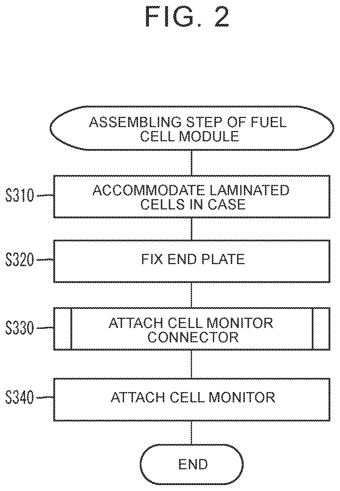
[0008]The attachment method may further include, before the positioning step, a step of rotationally moving an intermediate product including the cell so that a direction where the cell monitor connector is moved along the guide portion becomes a vertical direction. With such a configuration, the positioning step can be easily performed.

Problems solved by technology

In the technique in the related art, if the positioning is displaced toward either one of the walls, the cell monitor connector and the either one of the walls interfere with each other, so that the cell monitor connector cannot be inserted into the notch.
On this account, it is necessary for an operator to position the cell monitor connector by taking the measure of a positional relationship between the cell monitor connector and the walls, and thus, workability is low.

Method used


Image

  • Method of manufacturing a fuel cell module
  • Method of manufacturing a fuel cell module
  • Method of manufacturing a fuel cell module

Examples


Embodiment Construction

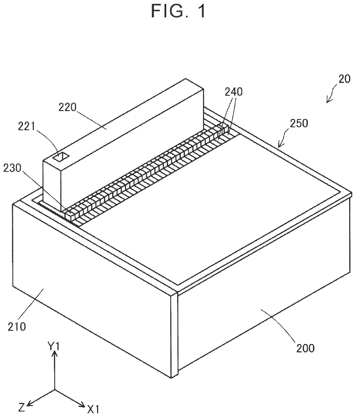
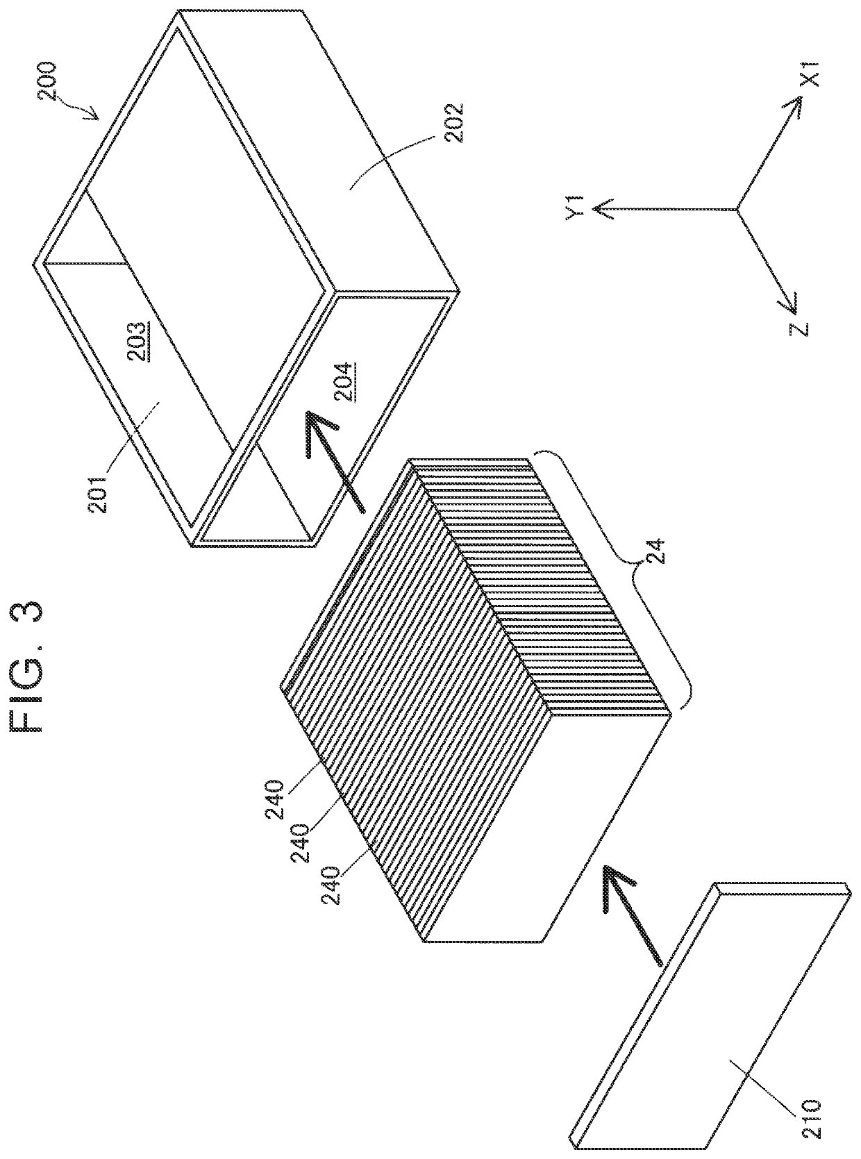
[0022]FIG. 1 is a perspective view illustrating a fuel cell module 20. The fuel cell module 20 includes a case 200, an end plate 210, a cell monitor 220, a plurality of cell monitor connectors 230, and a plurality of cells 240. All the cells 240, the case 200, and the end plate 210 are also collectively referred to as an intermediate product 250.

[0023]The cells 240 are accommodated in the case 200. The cell monitor 220 is fixed to an upper part of the case 200. Each of the cell monitor connectors 230 is a component electrically connected to a corresponding cell 240 for a fuel cell so as to measure a power generation voltage. Each of the cell monitor connectors 230 is connected to the cell monitor 220 via a cable 239 (FIG. 7, and so on).

[0024]An X1-Y1-Z coordinate system that is a right-handed rectangular coordinate system is defined as illustrated in FIG. 1. A Z-X1 plane is parallel to a horizontal plane. A positive side in a Y1-direction indicates an upper side in a vertical direct...


PUM

PropertyMeasurementUnit
α degreesaaaaaaaaaa
thicknessaaaaaaaaaa
thicknessaaaaaaaaaa

Abstract

A cell monitor connector is inserted with a first surface following a guide portion. When the cell monitor connector is further inserted, the cell monitor connector makes contact with a projection portion. In a state where the attachment is completed, the projection portion is elastically deformed so as to press a second surface. Due to this force, the cell monitor connector is held such that it is sandwiched between the projection portion and the guide portion.

Description

INCORPORATION BY REFERENCE[0001]The disclosure of Japanese Patent Application No. 2017-202365 filed on Oct. 19, 2017 including the specification, drawings and abstract is incorporated herein by reference in its entirety.BACKGROUND1. Technical Field[0002]This disclosure relates to an attachment method of a cell monitor connector to a cell of a fuel cell and a fuel cell module.2. Description of Related Art[0003]Japanese Unexamined Patent Application Publication No. 2013-120655 (JP 2013-120655 A) describes a technique in which a notch is provided in a corner of a frame member constituting a cell of a fuel cell, and a cell monitor connector is attached, by insertion, to a separator exposed from the notch. In a state where the cell monitor connector is attached, the notch includes walls between which opposite side surfaces of the cell monitor connector are sandwiched. A gap between the walls is slightly larger than the width of the cell monitor connector. On this account, when the cell m...

Claims


Application Information

Patent Timeline
Patent Type & Authority Patents(United States)
IPC IPC(8): H01M8/04313H01M8/0273H01M8/00H01M8/0202H01M8/0206
CPCH01M8/006H01M8/0202H01M8/0273H01M8/04313H01M8/0206H01M8/04664H01M8/04671H01M8/04686Y02E60/50Y02P70/50
Inventor SUGITA, KAZUMI
Owner TOYOTA JIDOSHA KK
Learn More