Electromagnetic switch device for starter

a technology of electric switch and starter, which is applied in the direction of engine starters, machines/engines, relays, etc., can solve the problems of difficult wiring arrangement and difficulty in ensuring a space, and achieve the effects of improving vehicle mountability, vibration resistance, and reducing the sub-coil siz

Inactive Publication Date: 2019-07-09
MITSUBISHI ELECTRIC CORP
View PDF6 Cites 0 Cited by
  • Summary
  • Abstract
  • Description
  • Claims
  • Application Information

AI Technical Summary

Benefits of technology

[0017]In the electromagnetic switch device for starter according to the present invention, since the main contact chamber and the sub coil are arranged in parallel in the radial direction with a partition wall provided therebetween in the terminal block, an effect of downsizing the sub coil is obtained, and since there is no protrusion in the axial direction, vehicle mountability is improved and vibration resistance is also improved.

Problems solved by technology

However, it is often difficult to ensure a space for providing the auxiliary relay in an engine chamber, and also it is often difficult to arrange the wirings.

Method used


Image

  • Electromagnetic switch device for starter
  • Electromagnetic switch device for starter
  • Electromagnetic switch device for starter

Examples


embodiment 1

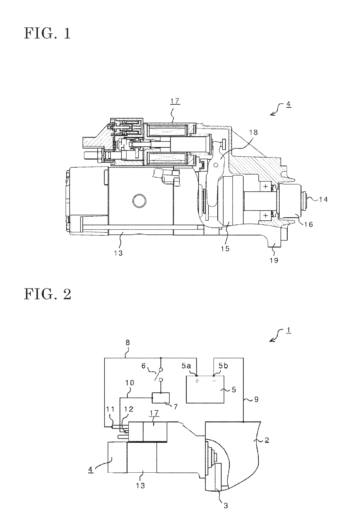
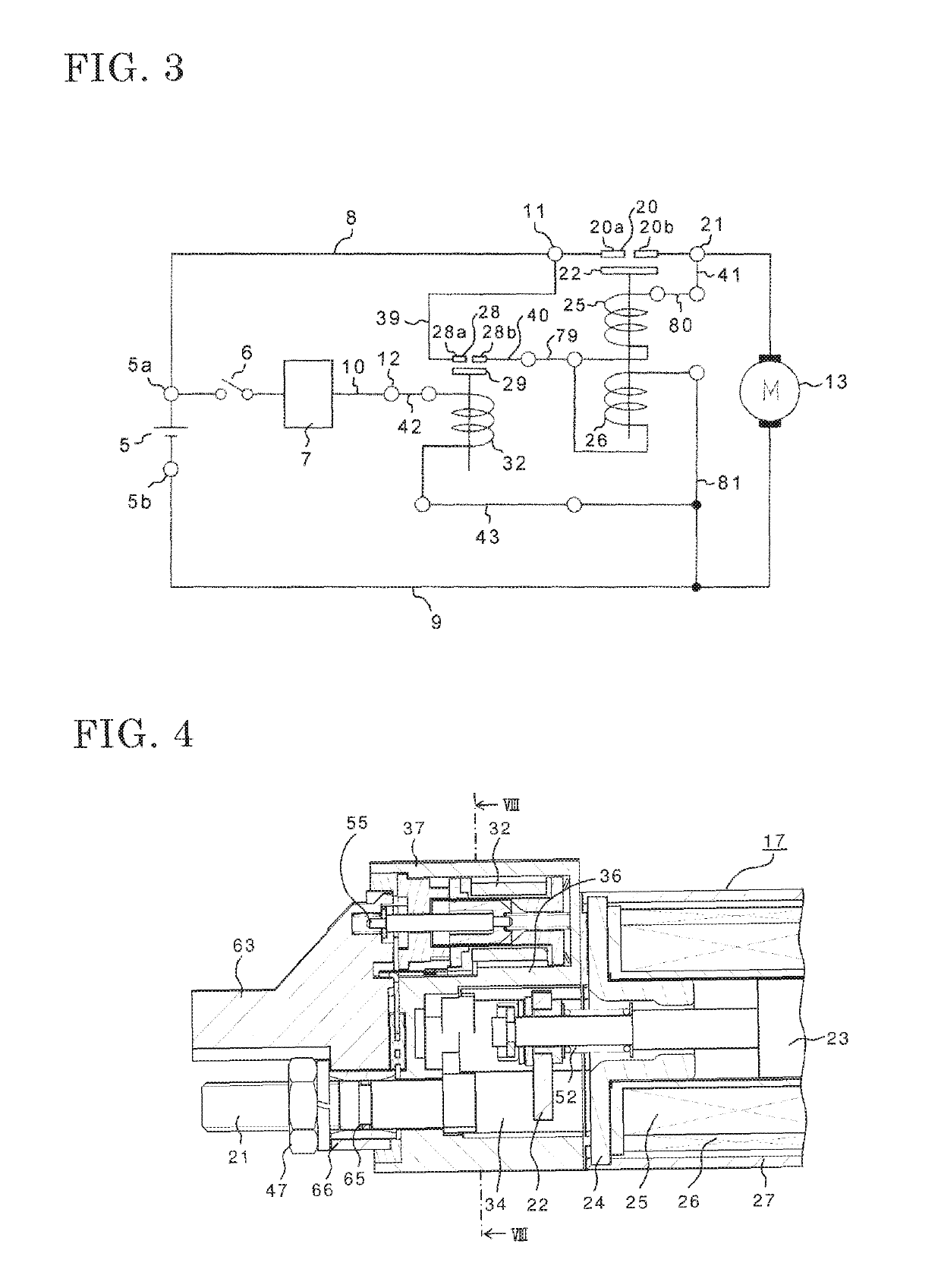
[0050]In FIGS. 1 to 16, an internal combustion engine device 1 includes an engine 2, a ring gear 3, a starter 4, a battery 5, a key switch 6, a control device 7, a battery plus wire 8, a battery minus wire 9, and an S circuit (+) wire 10.

[0051]The engine 2 is an internal combustion engine, and since the engine 2 cannot be started by itself, the engine 2 starts self-rotation by receiving a rotational force from the starter 4 via the ring gear 3.

[0052]The ring gear 3 transmits the rotational force from the starter 4 to the engine 2, and is directly connected to the engine 2.

[0053]The starter 4 generates a rotational force by power from the battery 5, and transmits the rotational force to the engine 2 via the ring gear 3.

[0054]The battery 5 is a secondary battery storing power for rotating the starter 4, and is electrically connected to the starter 4 via the battery plus wire 8 and the battery minus wire 9.

[0055]The key switch 6 causes the starter 4 to rotate when turned on, and causes...

embodiment 2

[0182]Next, the configuration of an electromagnetic switch device for starter according to embodiment 2 will be described.

[0183]The internal combustion engine device 1 in embodiment 1 has a so-called body-ground configuration in which the connection surface of the engine 2 with the front bracket 19 of the starter 4 forms a ground circuit. Meanwhile, in some internal combustion engine devices, a ground-floating-type starter may be used in which there is no electric connection between the starter and the engine.

[0184]In this case, on the minus side of the motor circuit of the starter and the minus side of the electric circuit of the electromagnetic switch device for starter, a dedicated terminal (E terminal) and the battery minus terminal 5b are electrically connected.

[0185]Embodiment 2 is applied to such an internal combustion engine device. Here, points modified from embodiment 1 will be described.

[0186]In FIGS. 17 to 22, in the internal combustion engine device 1 in embodiment 2, i...

embodiment 3

[0196]Next, the configuration of an electromagnetic switch device for starter according to embodiment 3 will be described.

[0197]In the electromagnetic switch device 17 for starter in embodiment 1, operation of the electromagnetic switch device for starter is controlled by opening and closing the circuit on the upstream side (S terminal 12 side) of the sub coil 32. In embodiment 3, operation of the electromagnetic switch device for starter is controlled by opening and closing the circuit on the minus side (connector (E) 43 side) of the sub coil 32. Thus, the control method in embodiment 1 is called a plus control method, whereas the control method in embodiment 3 is called a minus control method.

[0198]In FIG. 23 to FIG. 27, in addition to the configuration in embodiment 1 according to embodiment 2, the internal combustion engine device includes an S circuit (−) wire 33, and the electromagnetic switch device 17 for starter includes an E1 terminal 72.

[0199]In embodiment 1, the connecto...


PUM


Abstract

Provided is an electromagnetic switch device for starter in which an auxiliary relay is provided and which has a small size and can be easily manufactured. The electromagnetic switch device for starter includes: a main contact chamber forming a space in which a pair of main fixed contacts are located and a main movable contact can move; and a sub contact chamber forming a space in which a pair of sub fixed iron cores (A), (B) are located and a sub movable contact can move; and a cylindrical terminal block in which the main contact chamber and the sub coil are arranged so as to be adjacent to each other in the radial direction with a partition wall provided therebetween and separating the sub coil and the main contact chamber from each other.

Description

CROSS REFERENCE TO RELATED APPLICATIONS[0001]This application is a National Stage of International Application No. PCT / JP2015 / 060847 filed Apr. 7, 2015, the contents of all of which are incorporated herein by reference in their entirety.TECHNICAL FIELD[0002]The present invention relates to an electromagnetic switch device for starter, used for a starter for starting an engine provided to an automobile, for example.BACKGROUND ART[0003]Conventionally, an electromagnetic switch device for starter, used for a starter for starting a large-displacement engine of, in particular, a bus, a truck, or the like, needs to be supplied with large current for causing the electromagnetic switch device to operate, and a relay called an auxiliary relay, which has a smaller size than the electromagnetic switch device for starter, is used as current supplying means therefor.[0004]The auxiliary relay is provided near the electromagnetic switch device for starter and is connected via wirings to form an el...

Claims


Application Information

Patent Timeline
Patent Type & Authority Patents(United States)
IPC IPC(8): H01H50/42H01H50/40H01H50/02H01H51/06F02N15/06H01H50/14F02N11/08H01H50/44F02N15/02H01H47/22
CPCF02N11/087F02N15/067H01H50/023H01H50/14H01H50/40H01H50/42H01H51/065F02N11/0851H01H50/443F02N11/0818F02N11/0825F02N15/02F02N15/063F02N2011/0892H01H47/22F02N15/006
Inventor MORIMOTO, YOSHIHIRO
Owner MITSUBISHI ELECTRIC CORP
Why Eureka
Try Eureka