Puck handling device

a technology of a handling device and a spherical handle, which is applied in the direction of conveyors, rotary conveyors, conveyor parts, etc., can solve the problems of inflexibility, limited system throughput, and inability to use the diverted disc, etc., and achieves high friction

Inactive Publication Date: 2019-07-30
FLEXLINK
View PDF17 Cites 1 Cited by
  • Summary
  • Abstract
  • Description
  • Claims
  • Application Information

AI Technical Summary

Benefits of technology

[0013]By this first embodiment of the puck handling device according to the invention, a puck handling device that can transfer a puck from one of two conveyors to any of the two conveyors is provided. With such a puck handling device, the puck handling disc can hold the puck as a regular diverter disc in order to be able to transfer a puck from a first conveyor to the same first conveyor or from a second conveyor to the same second conveyor. The puck handling disc can further grip the puck firmly, such that the puck is fixed in the recess of the puck handling disc. In this way, the puck handling device is able to transfer a puck from a first conveyor to a second conveyor or from a second conveyor to a first conveyor. The puck handling device can further bypass the flow of one conveyor and block the flow of the other conveyor.
[0016]In the holding state, the recess will be larger than the puck that is to be held, such that the puck can easily enter the recess and exit the recess. This state is used when a puck is to be transferred from a first conveyor to the same first conveyor. The puck handling disc will in this state forward a puck from the pick-up position of the first conveyor to the release position of the first conveyor, as a regular diverter disc, and will at the same block the remaining pucks of the first and the second conveyors.
[0017]In the gripping state, the recess will have the same size as the puck that is to be held, such that the puck is firmly held in the recess. This is achieved in that the two cut-outs of the two semi-circular discs are rotated somewhat towards each other when a puck has entered the recess, such that the cut-outs will bear against the side walls of the puck. This gripping state is used when a puck is to be transferred from a first conveyor to a second conveyor or from a second conveyor to a first conveyor. The puck handling disc will in this state grip the puck such that the puck will not exit the recess when the puck is at the first release position of the first conveyor. Instead, the puck will be further transferred to the second release position of the second conveyor, where the puck will be released by rotating the two semi-circular discs somewhat away from each other such that he recess is enlarged, which allows the puck to exit the recess.
[0019]The depth of the semi-circular recess is preferably larger than the radius of a puck that is to be held by the recess. The depth of the recess is preferably 5-15% larger than the radius of the puck, and can be even larger depending on the size of the puck handling disc. This will allow the outer edges of the recess to extend inwards somewhat, such that the distance between the outer edges is somewhat smaller than the diameter of the puck that is to be held. This will ensure that the puck is held in a firm and secure way by the puck handling disc. The outer edges of the recess will ensure that the puck will not exit the recess by accident, since the puck will not only be held by friction but will also be clasped between the outer edges of the recess.
[0020]It is also possible to let the depth of the recess correspond to the radius of the puck that is to be held. In this way, the puck will be held only by friction in the recess. The bearing surface of the recess may also be coated with a high friction material that will help to hold the puck in the recess when the puck handling disc is arranged in the gripping state.
[0021]The puck handling disc comprises a first semi-circular disc arranged on a first shaft and a second semi-circular disc arranged on a second shaft. The first shaft and the second shaft are concentric and are aligned with the centre axis of the puck handling disc. The outer circumferential of the puck handling disc will follow a circular path when the puck handling disc is rotated, and the outer circumferential of both the semi-circular discs will thus follow the same circular path when they are rotated. With a smooth outer circumferential surface, the puck handling disc can be rotated with pucks bearing against it. This will thus allow the puck handling disc to be used as a stop member for pucks conveyed by any or both of the conveyors.

Problems solved by technology

One disadvantage of such a system is that it is not very flexible.
In such a system, a diverted disc cannot be used.
Such a solution will require several components and will be relatively slow such that the throughput of the system will be limited.

Method used


Image

  • Puck handling device
  • Puck handling device
  • Puck handling device

Examples


Embodiment Construction

[0032]The embodiments of the invention with further developments described in the following are to be regarded only as examples and are in no way to limit the scope of the protection provided by the patent claims. References such as longitudinal, horizontal, vertical, right, left etc. refer to directions of a conveyor in normal use.

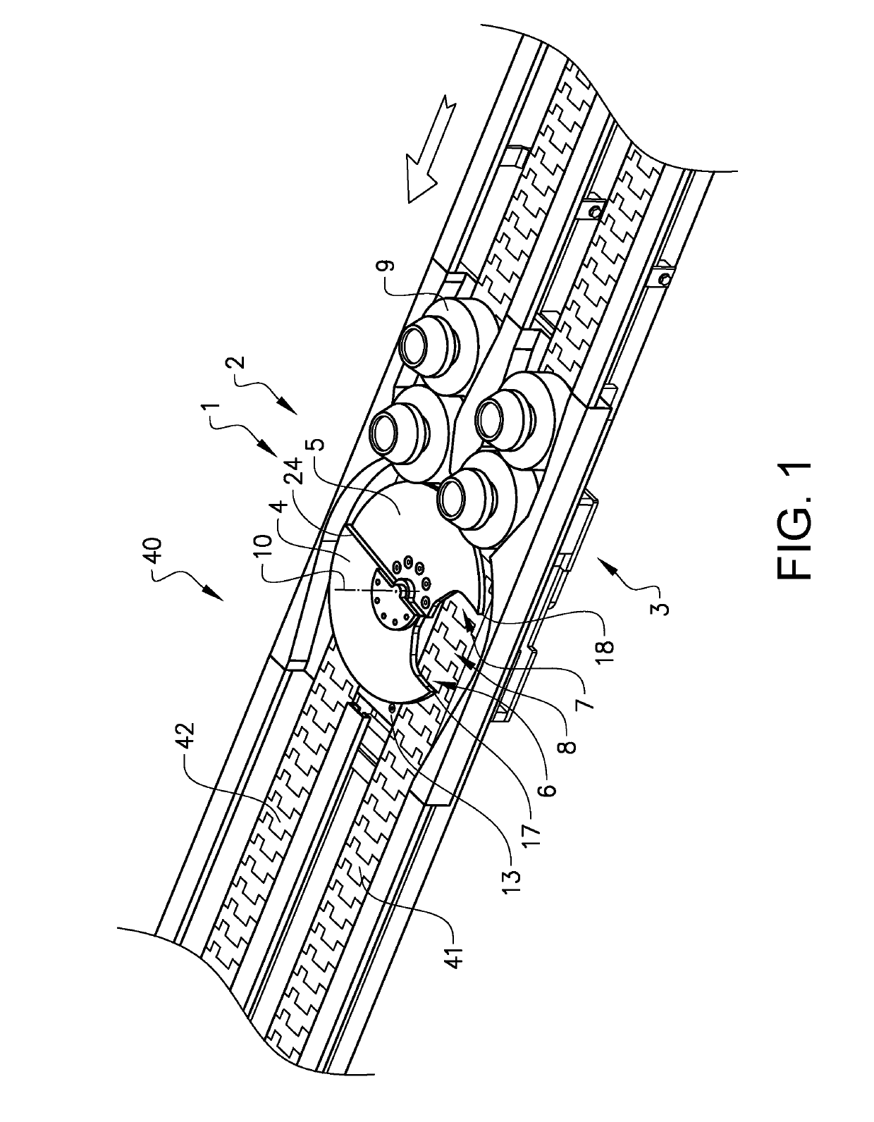
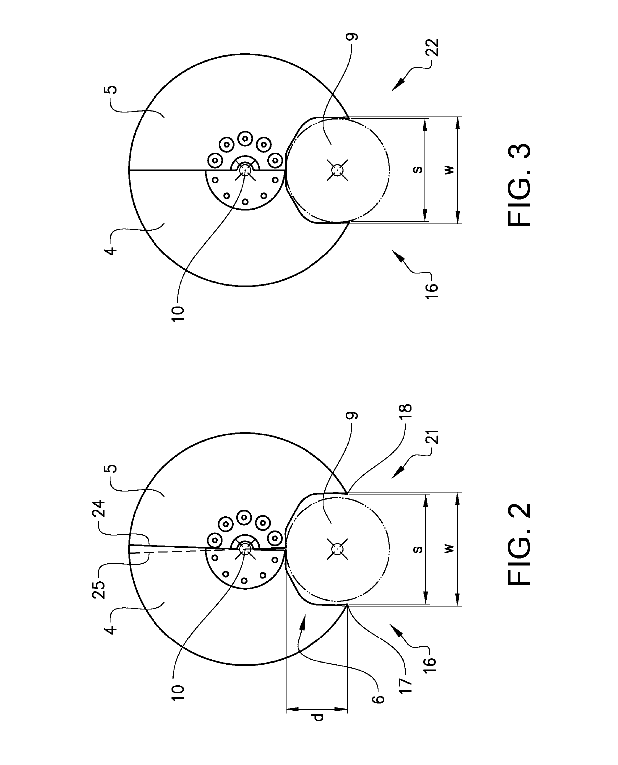
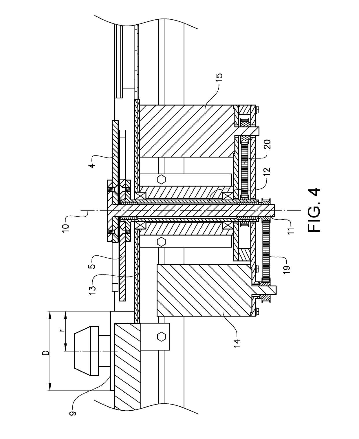
[0033]FIG. 1 shows a view of a conveyor system 40 comprising a puck handling device 1 according to the invention, FIGS. 2 and 3 show details of a puck handling disc, and FIG. 4 shows a cross section of a puck handling device.

[0034]The puck handling device 1 comprises a puck handling disc 2 and a drive means 3 for rotating the puck handling disc. The puck handling disc is in a first example arranged between a first conveyor 41 and a second conveyor 42, which are both conveying pucks in the same direction, indicated with an arrow. The puck handling disc is positioned at a distance above the conveyor surface, which will allow a wider part of the puck to pass...


PUM


Abstract

Puck handling device for a conveyor system, comprising a puck handling disc and a drive means for rotating the puck handling disc, where the puck handling disc comprises a first semi-circular disc comprising a first cut-out and a second semi-circular disc comprising a second cut-out, where the first semi-circular disc and the second semi-circular disc are individually rotatable by the drive means, and where the first cut-out and the second cut-out forms a recess adapted to hold a puck when the puck handling disc is arranged in a first holding state. The advantage of the invention is that a puck handling device adapted to direct a puck from any of two infeed conveyors to any of two outfeed conveyors is provided. This allows for a flexible and quick handling of pucks.

Description

PRIORITY APPLICATIONS[0001]This application is a U.S. National Stage Filing under 35 U.S.C. 371 from International Application No. PCT / SE2017 / 050305, filed on Mar. 29, 2017, and published as WO2017 / 176193 on Oct. 12, 2017, which claims the benefit of priority to Swedish Application No. 1650470-6, filed on Apr. 7, 2016; the benefit of priority of each of which is hereby claimed herein, and which applications and publication are hereby incorporated herein by reference in their entirety.TECHNICAL FIELD[0002]The present invention relates to a puck handling device for a conveyor system.BACKGROUND ART[0003]Conveying devices, such as those which are used for moving objects between different stations in a factory, usually comprise a conveying track in the form of a belt or a chain. The conveying tracks can be recessed in a trench with vertical side surfaces. Alternatively, they can be located on the horizontal upper surfaces of the trench or arranged in some other way. The objects to be con...

Claims


Application Information

Patent Timeline
Patent Type & Authority Patents(United States)
IPC IPC(8): B65G47/71B65G47/68B65G47/84
CPCB65G47/846B65G47/71B65G47/681B65G29/00B65G2201/0261
Inventor ECKERSTROM, SVEN-ERIKOHMAN, MICHAEL
Owner FLEXLINK
Why Eureka
Try Eureka