Drive arrangement for an endoscopic shaft-type instrument

a technology of endoscopic shaft and drive arrangement, which is applied in the direction of couplings, mechanical devices, gearing, etc., can solve the problems of disadvantageous size of the instrument housing, and achieve the effect of simple connection

Active Publication Date: 2019-08-06
RICHARD WOLF GMBH
View PDF24 Cites 0 Cited by
  • Summary
  • Abstract
  • Description
  • Claims
  • Application Information

AI Technical Summary

Benefits of technology

[0008]The basic idea of the invention lies in aligning the housing shafts obliquely to the drive shafts which are drive connected to them. Hereby, the direction, in which the housing shafts are obliquely aligned to the drive shafts, is basically arbitrary. One preferably envisages setting all housing shafts in an oblique manner. This oblique setting or positioning of the housing shafts permits a large design freedom with regard to the shaping of the instrument housing and, given a suitable alignment of the housing shafts, permits the creation of instrument housings which are comparatively small. A complete unit of the instrument housing and drive unit, in the case of a suitable oblique positioning of the housing shafts, can moreover be designed such that the shank instrument can be applied with those operations, with which the shank of these instruments must be introduced into the body of a patient at an as shallow as possible angle to the surface of the body of this patient.
[0010]A shaping of the instrument housing, with which this tapers into a tip, in a plane normal to the longitudinal extension of the instrument shank is particularly advantageous. Hereby, the instrument shank is usefully arranged in the direct vicinity of the tip which is formed on the instrument housing. This design permits several shank instruments to be used simultaneously in a restricted space, for example with a single port operation. Thus, for example, already three shank instruments can be applied in the direct proximity to one another, if the instrument housing tapers (in a pointed manner) at an angle of 120°. Typically, the possibility of applying even more shank instruments next to one another in a restricted space is given due to the reduction of the angle.
[0022]Usefully, a second fitting bore which crosses the fitting bore running in the joining direction of the instrument housing and drive housing there is formed on the drive housing, wherein a locking pin which in a locking position engages into a recess formed on the closure pin is displaceably guided in this second fitting bore. The instrument housing and the drive housing are fixedly connected to one another by way of this, wherein an actuation head which is formed at the end of the locking pin and which protrudes at the outer side of the drive housing and is thus easily accessible permits a simple release of the connection of the instrument housing and drive housing.

Problems solved by technology

This size of the instrument housing has been found to be disadvantageous if several of these shank instruments have to be commonly applied in a restricted space, as is the case for example with single port operations, with which the shank instruments are simultaneously led to the field of operation via a common body opening.

Method used


Image

  • Drive arrangement for an endoscopic shaft-type instrument
  • Drive arrangement for an endoscopic shaft-type instrument
  • Drive arrangement for an endoscopic shaft-type instrument

Examples


Embodiment Construction

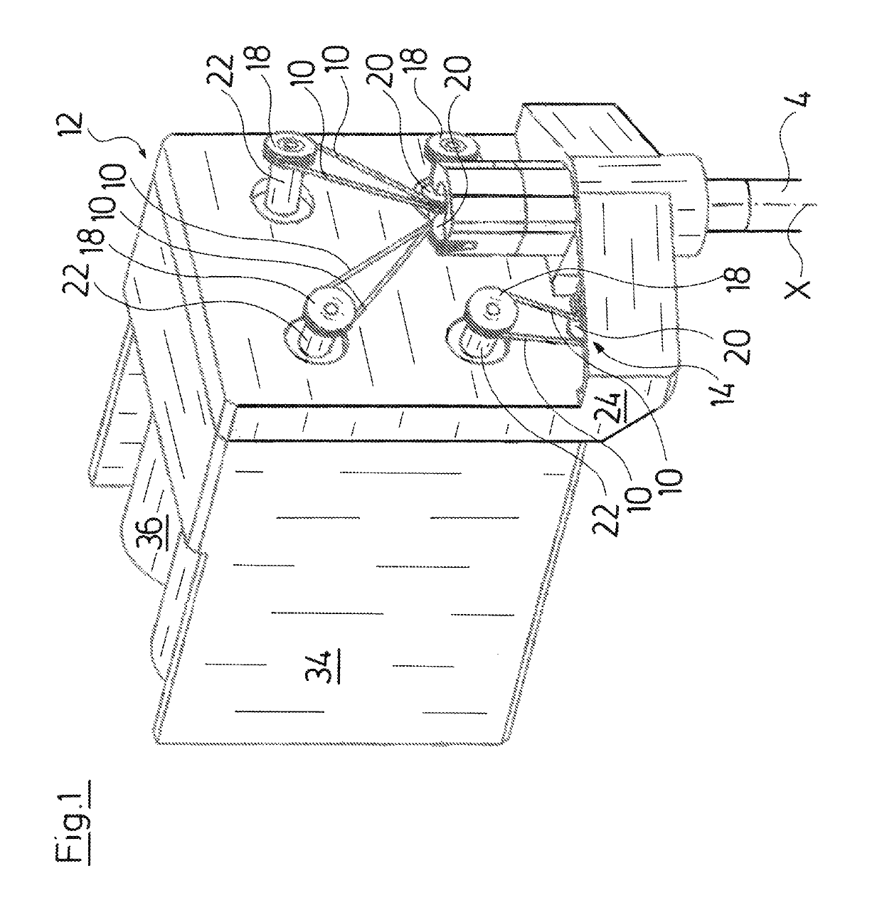
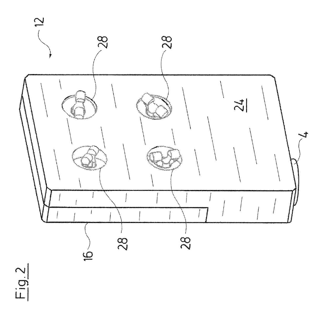
[0049]The endoscopic shank instrument which is represented in the FIGS. 1 and 2 is provided for the arrangement on a robot arm 2 of a surgical operation robot (FIGS. 20, 22 and 23). It comprises an elongate, rigid instrument shank 4. The instrument shank in FIGS. 1 and 2 has been almost completely omitted for purposes of a better overview, but it corresponds to the instrument shank 4 of the endoscopic shank instrument which is represented in FIGS. 21 to 23. With regard to the instrument shank 4 it is the case of a hollow shank. As with the shank instrument represented in FIGS. 21 to 23, an instrument head 6 with angular bending kinematics 7 and with a tool 8 is also arranged on the distal shank end of the shank instrument which is represented in FIGS. 1 and 2. The tool 8 can be angled relative to the instrument shank 4 by way of the angular bending kinematics 7.

[0050]Pull means or pull device in the form of six pull cables 10 which are led through the instrument shank 4 into an inst...


PUM


Abstract

A drive arrangement for an endoscopic shaft instrument, preferably an instrument which is intended for use in connection with a surgical robot, has a drive arrangement that has an instrument housing (12) on a proximal shaft end. At least one housing shaft (22) is mounted in the instrument housing (12). The shaft is drivingly connected to a traction device which is provided for controlling an instrument head on a distal shaft end. Furthermore, the drive arrangement has a drive unit having at least one drive shaft. The housing shaft (22) can be drivingly connected to said drive shaft. The at least one housing shaft (22) is oriented at an angle to the drive shaft (30) and the drive shaft can be drivingly connected thereto.

Description

CROSS REFERENCE TO RELATED APPLICATIONS[0001]This application is a United States National Phase Application of International Application PCT / DE2014 / 200625 filed Nov. 10, 2014 and claims the benefit of priority under 35 U.S.C. § 119 of German Application 10 2013 225 117.3 filed Dec. 6, 2013, the entire contents of which are incorporated herein by reference.FIELD OF THE INVENTION[0002]The invention relates to a drive arrangement for an endoscopic shank instrument with an instrument housing at the proximal shank end, with at least one housing shaft which is rotatably mounted in the instrument housing and which is repeatedly releasably drive-connected to a pull device, which pull device is provided at a distal shank end for control of an instrument head, and with a drive unit with at least one drive shaft, to which drive shaft the housing shaft is drive-connectable.BACKGROUND OF THE INVENTION[0003]Operation robots have been applied for some time now in the field of minimal-invasive surg...

Claims


Application Information

Patent Timeline
Patent Type & Authority Patents(United States)
IPC IPC(8): F16H19/06A61B34/00A61B34/30F16D3/26
CPCA61B34/30A61B34/70A61B34/71F16H19/06F16D3/26A61B2034/305A61B2034/301
Inventor WEHRHEIM, FRANKSCHWEIGERT, ALEXANDERPRESTEL, STEPHANMUNNIG, SORENLAMBERTZ, MATTHIASKORNER, EBERHARD
Owner RICHARD WOLF GMBH
Why Eureka
Try Eureka