Eureka AIR delivers breakthrough ideas for toughest innovation challenges, trusted by R&D personnel around the world.

Multifunction lamp unit and rear view device therewith

a multi-functional, lamp technology, applied in the direction of instruments, lighting and heating apparatus, other domestic objects, etc., can solve the problems of limiting the design of the lamp, affecting the tolerance of adjacent clearances, and affecting the construction cost of the known lamp, etc., to achieve large design freedom, easy manufacturing, and high light yield

Active Publication Date: 2019-12-17
SMR PATENTS S A R L
View PDF8 Cites 0 Cited by
  • Summary
  • Abstract
  • Description
  • Claims
  • Application Information

AI Technical Summary

Benefits of technology

[0013]In an aspect, a method for manufacturing a lamp for vehicles overcomes the disadvantages of the state of the art. For example, a lamp should be easy to manufacture and offer large freedom of design with high light yield.

Problems solved by technology

The construction of these known lamps is expensive.
In addition, welding processes negatively affect the tolerances of adjacent clearances.
The necessity of a weld seam or adhesive seam also limits the design of the lamps, as with a blinker in a side-view mirror arrangement of a vehicle.
Molding a coating on a film to produce a light window, such as a blinker, is complicated particularly since a fastening on a housing is also needed.

Method used


Image

  • Multifunction lamp unit and rear view device therewith
  • Multifunction lamp unit and rear view device therewith
  • Multifunction lamp unit and rear view device therewith

Examples


Embodiment Construction

[0067]The following detailed description is provided to assist the reader in gaining a comprehensive understanding of the methods, apparatuses, and / or systems described herein. Accordingly, various changes, modifications, and equivalents of the systems, apparatuses and / or methods described herein will be suggested to those of ordinary skill in the art. Also, descriptions of well-known functions and constructions may be omitted for increased clarity and conciseness.

[0068]The term “rearview” is here defined as a view of the surrounding area, which is not in the field of view of the driver, i.e. the directions opposing, left, right, below and above of the viewing direction, but can also comprise the view in the direction of the viewing direction of the driver and / or any combinations of the directions.

[0069]The term “driver” and “driver of the vehicle” relates here to the person controlling the main parameters of the vehicle, such as for example direction, speed and / or altitude, e.g. no...


PUM

PropertyMeasurementUnit
thicknessaaaaaaaaaa
thicknessaaaaaaaaaa
thicknessaaaaaaaaaa

Abstract

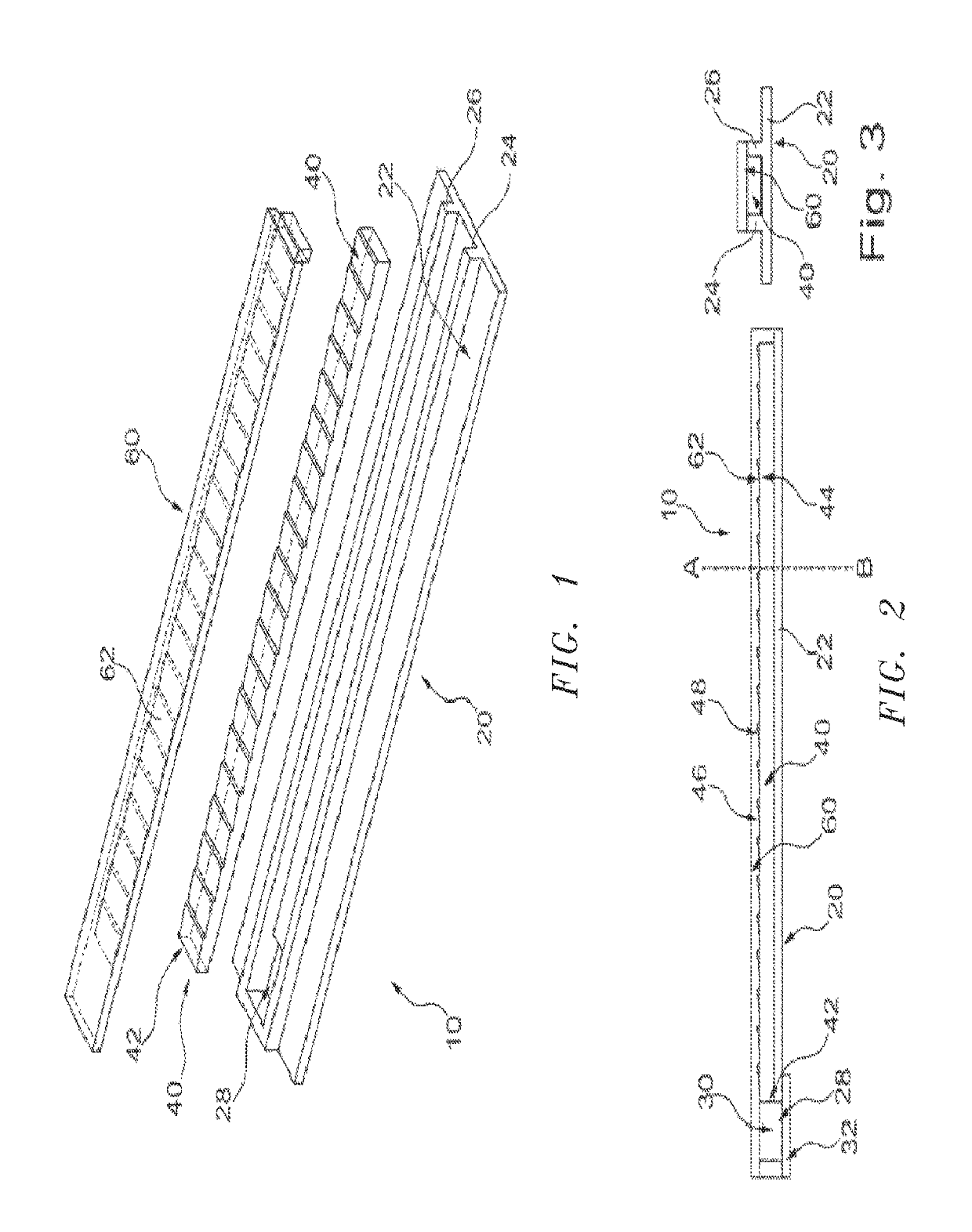
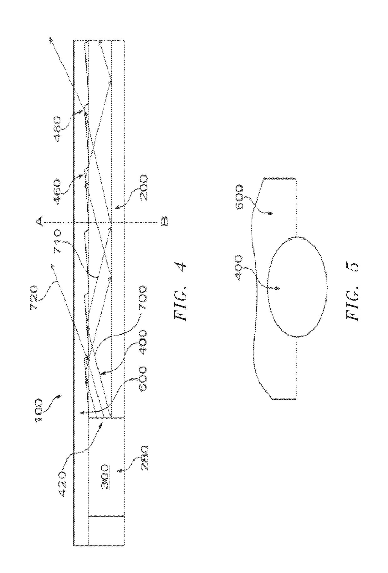
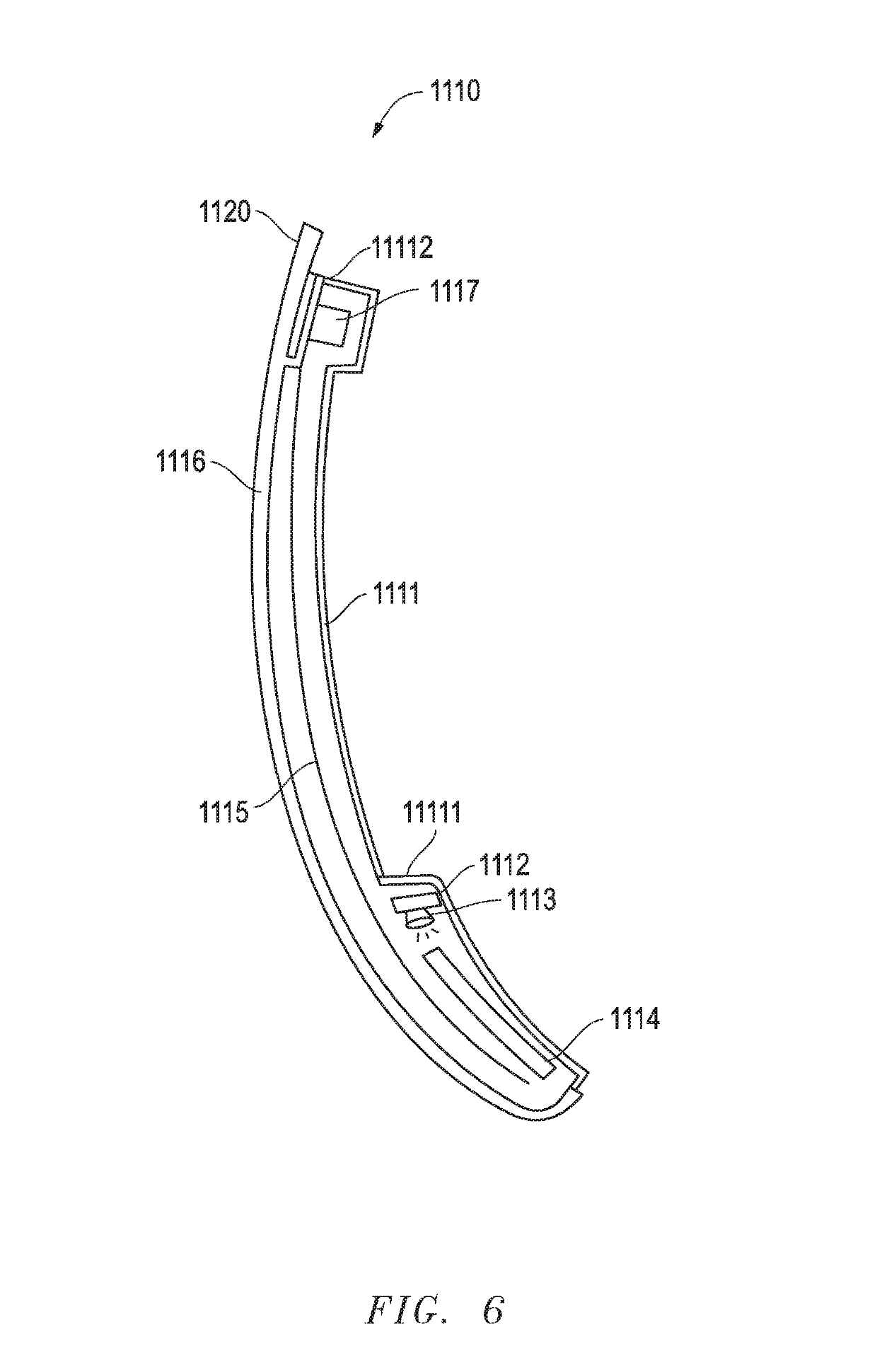
A multifunction lamp unit for a vehicle includes a housing, at least one light conductor with at least one illuminant provided by an LED on a printed circuit board, at least one light foil, and a clear lens. A method for manufacturing lamps for vehicles includes producing a housing, a light conductor, and a clear lens as one unit out of plastic in a 3-component injection procedure.

Description

CROSS-REFERENCE TO RELATED APPLICATIONS[0001]This application is a continuation-in-part of U.S. patent application Ser. No. 15 / 052,120, filed Feb. 24, 2016, which claims the benefit of foreign priority to European Patent Application No. 15156407.7, filed Feb. 24, 2015; and this application is a continuation-in-part of U.S. patent application Ser. No. 15 / 439,188, filed Feb. 22, 2017, which is a continuation-in-part of U.S. patent application Ser. No. 14 / 936,024, filed Nov. 9, 2015, which is a continuation-in-part of U.S. patent application Ser. No. 14 / 374,376, filed Jul. 24, 2014 and now issued as U.S. Pat. No. 9,181,616, which is a national stage entry of International Patent Application No. PCT / AU2013 / 000047, filed Jan. 24, 2013, which claims the benefit of foreign priority to Australian Patent Application No. 2012900267, filed Jan. 24, 2012, each of which is herein incorporated by reference in its entirety for all purposes.STATEMENT REGARDING FEDERALLY SPONSORED RESEARCH OR DEVELO...

Claims


Application Information

Patent Timeline
Patent Type & Authority Patents(United States)
IPC IPC(8): B60Q1/00B60Q1/38B60R1/06F21S45/50F21S43/239F21S43/14F21S43/19B29C45/16F21S43/247F21S43/245F21S43/237B60Q1/26B29D11/00F21S45/60F21V8/00B29L11/00B29L31/00F21W103/25
CPCF21S43/237B29D11/00682B60Q1/38B60Q1/2665B29D11/00663F21S43/245F21S43/239B29C45/16F21S43/14F21S45/50F21S43/19F21S43/195F21S43/247F21S45/60B60Q2400/40B29K2995/0031B29L2011/0016G02B6/0038B29L2031/747F21W2103/25G02B6/0065
Inventor NEGEL, RAIMUNDSCHMIERER, ARNEFRITZ, DANIELHERRMANN, ANDREAS
Owner SMR PATENTS S A R L
Why Eureka
Eureka Blog
Learn More