Method of constructing a tunable RF filter

a technology of rf filter and tunable filter, which is applied in the direction of semiconductor/solid-state device testing/measurement, magnetic bodies, instruments, etc., can solve the problems of machining techniques, heavy and expensive rf filter production methods, and increase process cost and complexity, so as to reduce the cost and complexity of the fabrication of rf output filters.

Active Publication Date: 2012-12-18
KMW INC
View PDF56 Cites 0 Cited by
  • Summary
  • Abstract
  • Description
  • Claims
  • Application Information

AI Technical Summary

Benefits of technology

[0005]It is an object of the present invention to reduce the cost and the complexity of the fabrication of an RF output filter.
[0006]The method for fabricating an RF filter that is disclosed herein eliminates the large and heavy aluminum body and its costly cover.
[0007]Specifically, the disclosed method includes fabricating a core body (for example, by molding or machining) preferably with a very low dissipation factor material, such as polystyrene plastic or polyethylene foam, and then forming a thin metallic body (for example, by plating) of a high strength metallic material over the exterior surface of the core body to obtain a metallic shell. The metallic shell surrounds the core body, thus eliminating the need for a cover.
[0013]Features can be designed into the metallic shell to render it locally compliant in a more predictable manner whereby it may be plastically deformed in a desired way without changing the overall configuration of the filter. The material for the fabrication of the metallic shell must be chosen to have an appropriate compliance to permit the localized plastic deformation. This approach would eliminate the need for tuning screws and would be very suitable for highly-automated manufacturing.
[0014]Filters that are fabricated according to the present invention would be significantly lighter and less costly. It should also be noted that a method according to the present invention could significantly reduce the complexity of filter designs and thus provide extensive design freedom for RF filter designers to design filters that are not possible and / or practical with traditional filter manufacturing methods. Thus, for example, the use of a core body will allow the filter designer to explore new and unique shapes for filter designs, which could not be fabricated by machining or die casting.
[0015]The manufacturability of core shapes is an important driver of filter designs today. Advantageously, a method according to the present invention may allow for the design of new filter shapes, which were previously excluded from consideration because of conventional manufacturing limitations.

Problems solved by technology

Both methods produce heavy and expensive RF filters.
Also, both methods further require the machining of a cover for the cavity filter, which is attached to the base of the machined aluminum part with a significant number of screws to guarantee an effective RF seal thereby increasing the cost and complexity of the process.
Another limitation of the conventional methods is the restriction imposed by conventional machining techniques, which typically require the cavity to have vertical walls with a radius along the bottom and side corners and a square corner (which is undesirable) where the cover seals to the top of the cavity.

Method used


Image

  • Method of constructing a tunable RF filter
  • Method of constructing a tunable RF filter
  • Method of constructing a tunable RF filter

Examples


Embodiment Construction

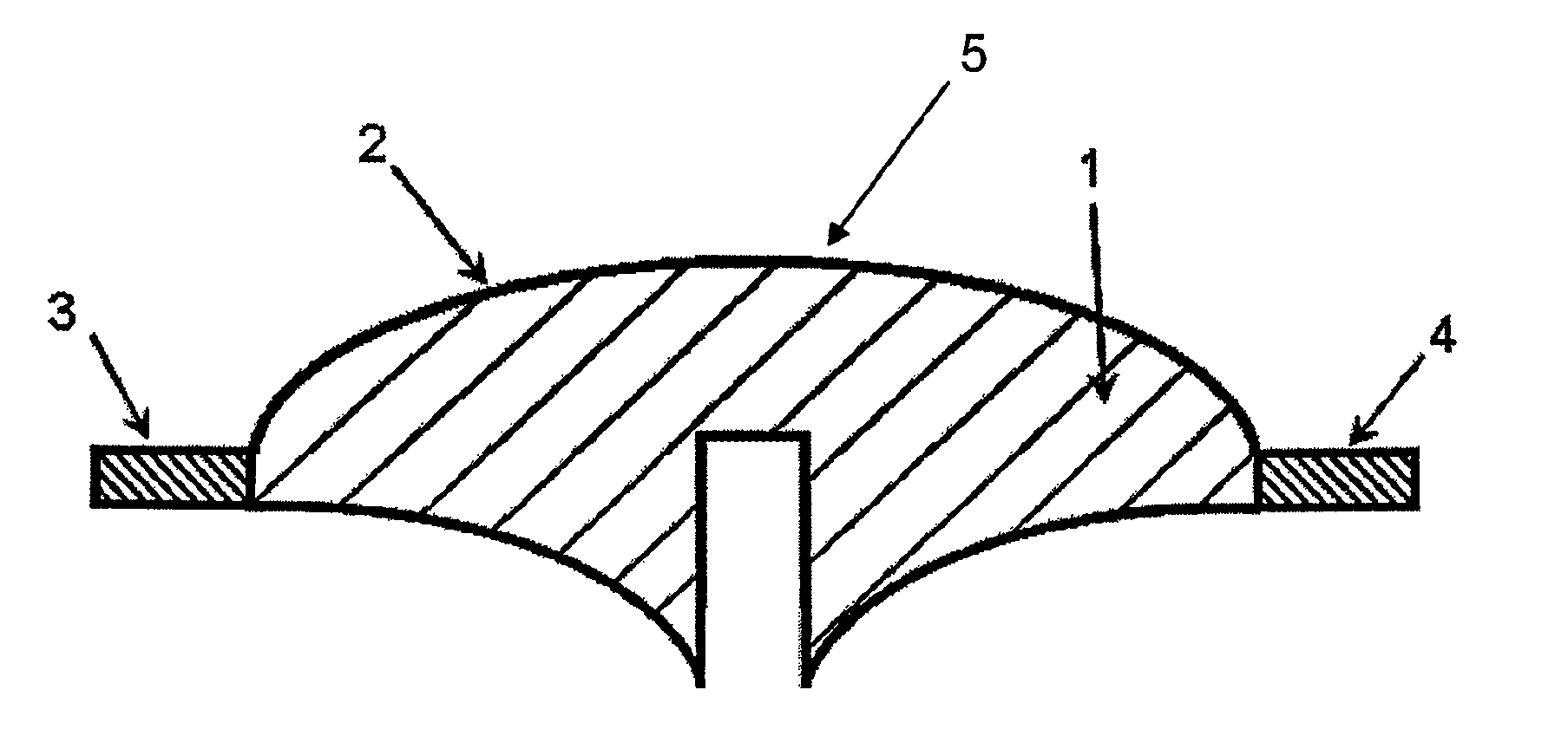
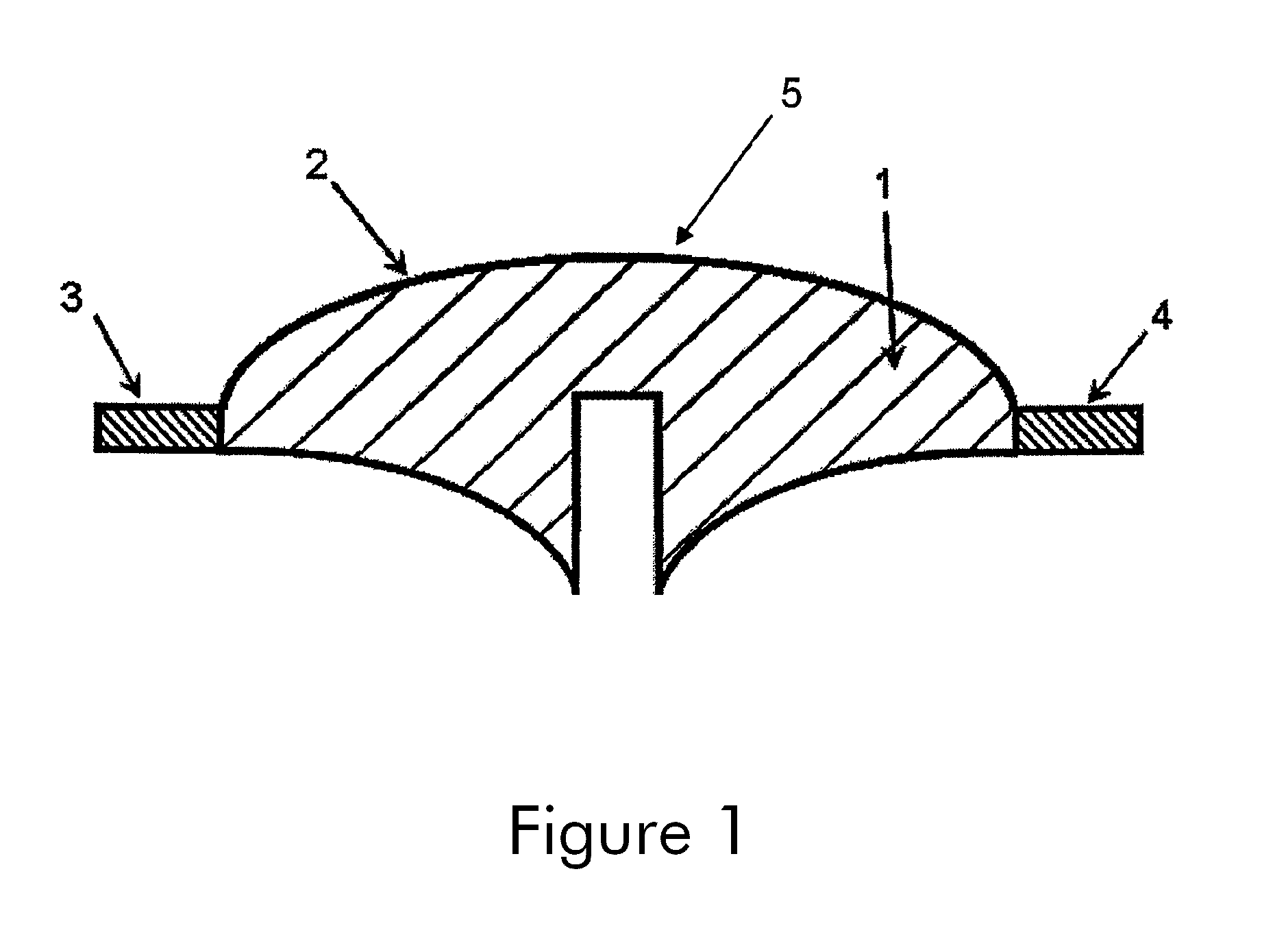
[0024]FIG. 1 depicts a cross-sectional view of an RF output filter 5 that is fabricated according to the present invention. RF output filter 5 may include a core body 1, which may be removable as further explained below, and a plastically deformable metallic shell 2 formed around and directly over the exterior surface of core body 1. Plastically deformable metallic shell 2 may include a layer of one metallic material, or two or more layers each composed of a different metallic material. The thickness and the material or materials used for forming metallic shell 2 may vary depending upon the actual design of filter 5. Note that, while FIG. 1 shows metallic shell 2 encasing core body 1, metallic shell 2 may include a perforation, or two or more perforations therein to provide access to the interior thereof. Such access may be used to remove core body 1, or used for the purpose allowing the mounting of connectors or the like to RF filter 5. FIG. 1 further shows an input port connector ...


PUM

PropertyMeasurementUnit
frequencyaaaaaaaaaa
metallicaaaaaaaaaa
electrical resistivityaaaaaaaaaa

Abstract

A method is disclosed for the fabrication of a tunable radio frequency (RF) power output filter that includes fabricating a core body and then forming a plastically deformable metallic shell over the exterior surface of the core body.

Description

CROSS REFERENCE TO RELATED APPLICATION AND CLAIM OF PRIORITY[0001]The present application claims benefit of and priority to U.S. Provisional Patent Application No. 61 / 273,821 entitled METHOD OF CONSTRUCTING AN RF FILTER filed Aug. 10, 2009, the entire contents of which are hereby incorporated by reference.FIELD OF THE INVENTION[0002]The present invention is directed to a method of constructing a power output filter for a radio frequency (RF) application, for example, in the cellular band or the microwave band. A method according to the present invention could also be used to fabricate combined transmit and receive filters.BACKGROUND OF THE INVENTION[0003]Today, most RF output filters for the cellular frequency band are manufactured either by machining cavities in large blocks of aluminum or by die casting large aluminum parts. Both methods produce heavy and expensive RF filters. Also, both methods further require the machining of a cover for the cavity filter, which is attached to t...

Claims


Application Information

Patent Timeline
Patent Type & Authority Patents(United States)
IPC IPC(8): G01R31/28
CPCH01P1/208H01P11/008H01P1/30H01P7/06Y10T29/49002Y10T29/4908Y10T29/49004Y10T29/49128
Inventor LAGROTTA, JAMES THOMASLAGROTTA, RICHARD T.
Owner KMW INC
Why Eureka
Try Eureka