Light efficiency methods for vehicular HTL systems
What is AI technical title?
AI technical title is built by Patsnap AI team. It summarizes the technical point description of the patent document.
a technology of htl system and light efficiency method, which is applied in the direction of transportation and packaging, lighting and heating apparatus, optical viewing, etc., can solve the problems of limiting the design of the lamp, affecting the tolerance of adjacent clearances, and affecting the construction cost of the known lamp, etc., to achieve easy manufacturing, large design freedom, and high light yield
Active Publication Date: 2021-04-06
SMR PATENTS S A R L
View PDF13 Cites 0 Cited by
Summary
Abstract
Description
Claims
Application Information
AI Technical Summary
This helps you quickly interpret patents by identifying the three key elements:
Problems solved by technology
Method used
Benefits of technology
Benefits of technology
[0011]In an aspect, a method for manufacturing a lamp for vehicles overcomes the disadvantages of the state of the art. For example, a lamp should be easy to manufacture and offer large freedom of design with high light yield.
Problems solved by technology
The construction of these known lamps is expensive.
In addition, welding processes negatively affect the tolerances of adjacent clearances.
The necessity of a weld seam or adhesive seam also limits the design of the lamps, as with a blinker in a side-view mirror arrangement of a vehicle.
Molding a coating on a film to produce a light window, such as a blinker, is complicated particularly since a fastening on a housing is also needed.
The respective systems may have various issues with light efficiency as light is either lost from the system or reflected inside the system.
The problems include that light pipes may have bright / dull spots that cannot be solved by shape changes due to restrictions such as customer styling, conversely the customer may desire variations in the illumination between parts of common shape.
Finally as the diffusion / light emission of the light pipe or similar is generally somewhat constant a large amount of light is wasted and must be masked in areas where no illumination is desired, such as near light sources.
Method used
Image
Click on the blue label to locate the original text in one second.
Reading with bidirectional positioning of images and text.
Examples
Embodiment Construction
[0074]The following detailed description is provided to assist the reader in gaining a comprehensive understanding of the methods, apparatuses, and / or systems described herein. Accordingly, various changes, modifications, and equivalents of the systems, apparatuses and / or methods described herein will be suggested to those of ordinary skill in the art. Also, descriptions of well-known functions and constructions may be omitted for increased clarity and conciseness.
[0075]The term “rearview” is here defined as a view of the surrounding area, which is not in the field of view of the driver, i.e. the directions opposing, left, right, below and above of the viewing direction, but can also comprise the view in the direction of the viewing direction of the driver and / or any combinations of the directions.
[0076]The term “driver” and “driver of the vehicle” relates here to the person controlling the main parameters of the vehicle, such as for example direction, speed and / or altitude, e.g. no...
PUM
Property
Measurement
Unit
refractive index
aaaaa
aaaaa
thickness
aaaaa
aaaaa
thickness
aaaaa
aaaaa
Abstract
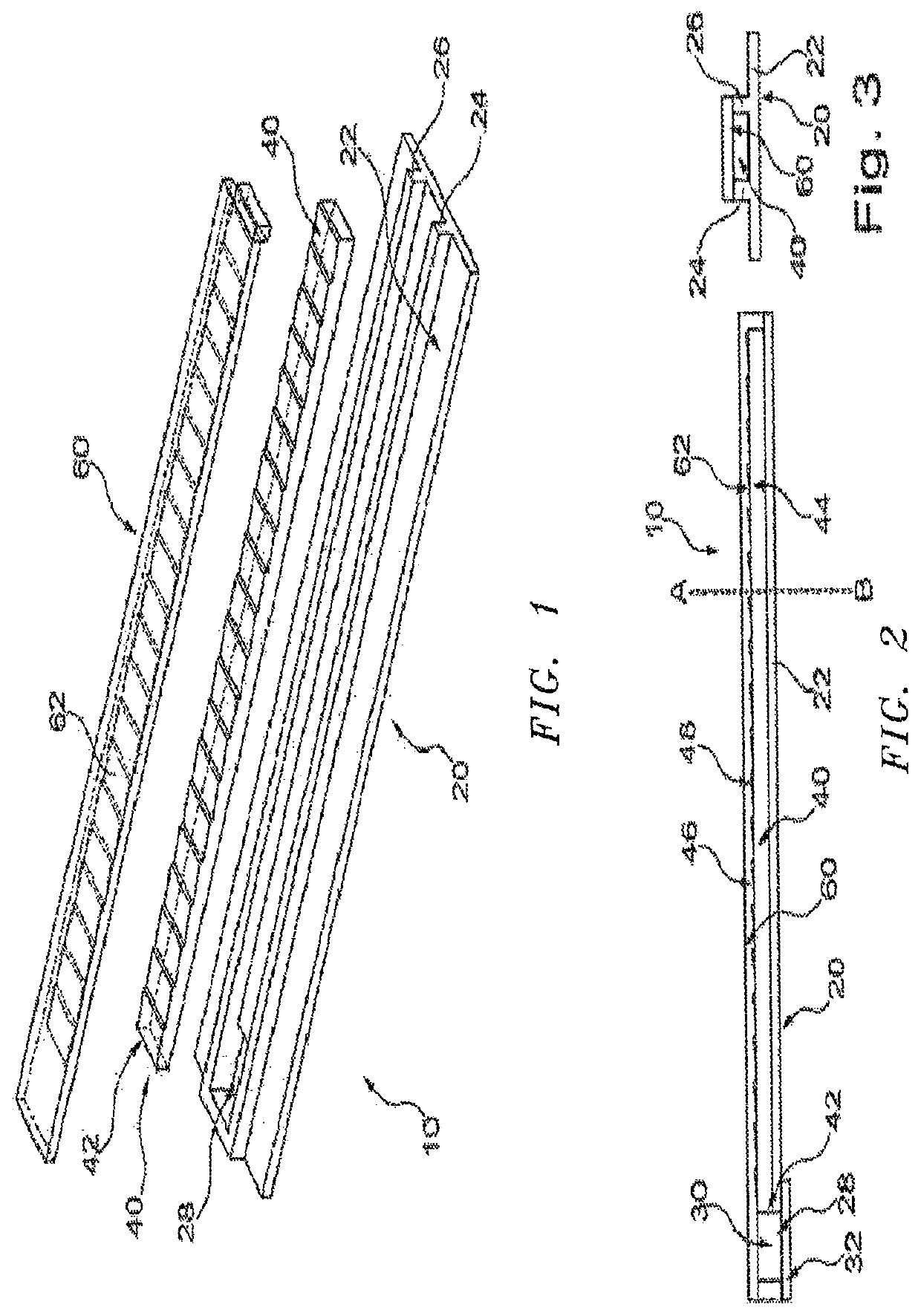
A multifunction lamp unit for a vehicle includes a housing, at least one light pipe together with at least one light source disposed at least partially within the housing, and a clear lens substantially enclosing the housing, the at least one light pipe and the at least one light source, the lens having an inner surface, an outer surface disposed opposite the inner surface and at least one of a continuous transparent and translucent coating on the outer surface.
Description
CROSS-REFERENCE TO RELATED APPLICATIONS[0001]This application is a continuation-in-part of U.S. patent application Ser. No. 15 / 956,091, filed Apr. 18, 2018, which is a continuation-in-part of U.S. patent application Ser. No. 15 / 589,043, filed May 8, 2017, which is a continuation-in-part of U.S. patent application Ser. No. 15 / 052,120, filed Feb. 24, 2016, which claims the benefit of foreign priority to European Patent Application No. 15156407.7, filed Feb. 24, 2015; and which also is a continuation-in-part of U.S. patent application Ser. No. 15 / 439,188, filed Feb. 22, 2017, which is a continuation-in-part of U.S. patent application Ser. No. 14 / 936,024, filed Nov. 9, 2015, which is a continuation-in-part of U.S. patent application Ser. No. 14 / 374,376, filed Jul. 24, 2014 and now issued as U.S. Pat. No. 9,181,616, which is a national stage entry of International Patent Application No. PCT / AU2013 / 000047, filed Jan. 24, 2013, which claims the benefit of foreign priority to Australian Pat...
Claims
Application Information
Patent Timeline
Application Date:The date an application was filed.
Publication Date:The date a patent or application was officially published.
First Publication Date:The earliest publication date of a patent with the same application number.
Issue Date:Publication date of the patent grant document.
PCT Entry Date:The Entry date of PCT National Phase.
Estimated Expiry Date:The statutory expiry date of a patent right according to the Patent Law, and it is the longest term of protection that the patent right can achieve without the termination of the patent right due to other reasons(Term extension factor has been taken into account ).
Invalid Date:Actual expiry date is based on effective date or publication date of legal transaction data of invalid patent.

