Backlight module and display apparatus

a backlight module and display device technology, applied in the field of display technology, can solve the problems of unstably bonded reflection sheet and and achieve the effect of easy loosening and o

Active Publication Date: 2019-08-06
TCL CHINA STAR OPTOELECTRONICS TECH CO LTD +1
View PDF16 Cites 0 Cited by
  • Summary
  • Abstract
  • Description
  • Claims
  • Application Information

AI Technical Summary

Benefits of technology

[0008]The object of the present invention is to provide a backlight module and a display apparatus to solve an existing problem in prior art. That is, when the increasingly narrow plastic frame and the reflection sheet are attached with double-sided adhesive, the fixing strength is affected by an external force resulting in the reflection sheet which is unstably bonded with the plastic frame and easily comes loose and off.
[0037]In comparison with the prior art, the present invention makes the extension portion of the reflective sheet work like a barb to tightly clasp the plastic frame and thereby the reflective sheet does not easily come off from the plastic frame due to the reflective sheet being extended toward the inner side surface of the plastic frame and fixedly bonded to the inner side surface of the plastic frame by double-sided adhesive, being extended toward the upper surface of the plastic frame and fixedly bonded to the upper surface of the plastic frame by double-sided adhesive as well as being outwardly extended toward the outer surface of the plastic frame and fixedly bonded to the outer surface of the plastic frame by double-sided adhesive. Therefore, even though the width of the plastic frame is further narrowed, it is still ensured that the reflection sheet is fixedly bonded on the plastic frame well in order to allow the border of the backlight module to become significantly thinner. Not only can the narrow frame design can be achieved, but also the optical films can meet the requirement of fixing strength at the same time. Furthermore, the utilization of light is raised.

Problems solved by technology

That is, when the increasingly narrow plastic frame and the reflection sheet are attached with double-sided adhesive, the fixing strength is affected by an external force resulting in the reflection sheet which is unstably bonded with the plastic frame and easily comes loose and off.

Method used


Image

  • Backlight module and display apparatus
  • Backlight module and display apparatus

Examples


first embodiment

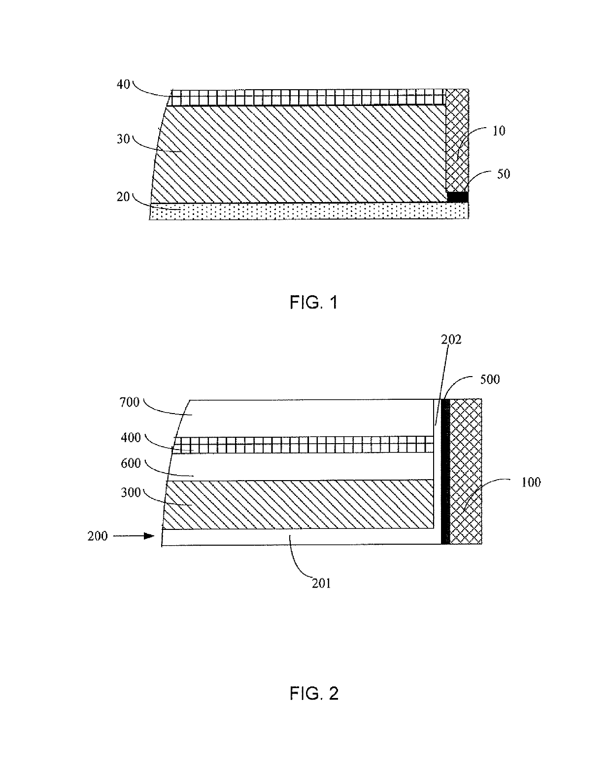
[0047]Referring to FIG. 2, a schematic diagram of a backlight module in accordance with a preferred embodiment provided by the present invention is illustrated. For ease of illustration, merely a portion concerning the embodiment of the present invention is shown.

[0048]The backlight module comprises: a plastic frame 100, a reflection sheet 200, a light guide plate 300, an optical film set, and a connecting member 500. The reflection sheet 200 includes a first body 201 and a second body 202, in which the first body 201 and the second body 202 are integrally formed. The second body 202 is disposed on the side of the first body 201, and the first body 201 and the second body 202 define and embrace an upwardly-opened cavity. The light guide plate 300 and the optical film are disposed inside the cavity enclosed by the body 201 and second body 202. The reflection sheet 200, the light guide plate 300, and the optical film set are disposed inside the plastic frame 100. The light guide plate...

second embodiment

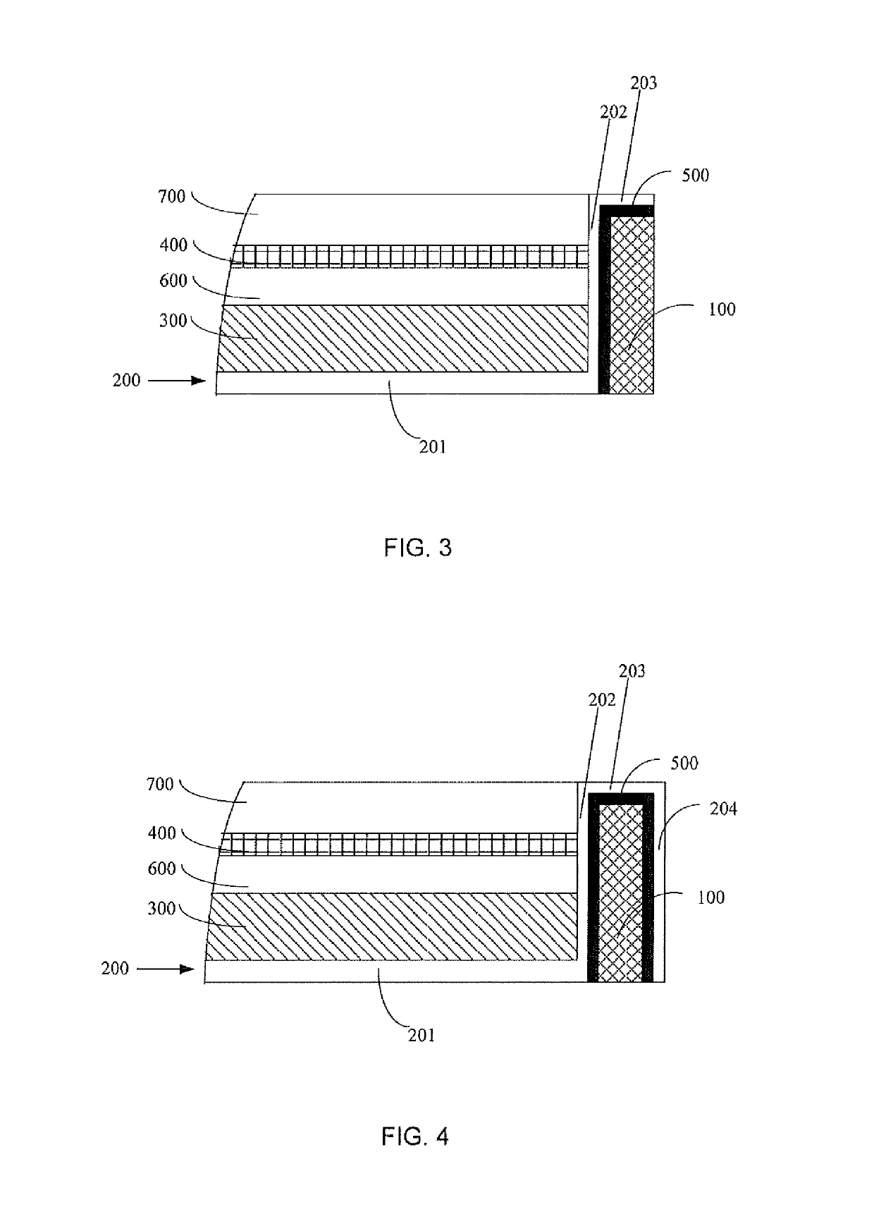
[0054]Referring to FIG. 3, a schematic diagram of a backlight module in accordance with a preferred embodiment provided by the present invention is illustrated. For ease of illustration, merely a portion concerning the embodiment of the present invention is shown. The second embodiment is similar to the first embodiment described above, and the difference is that:

[0055]The reflection sheet 200 also includes a third body 203 formed by means of extending the second body 202 toward the upper surface of the plastic frame 100, and the third body 203 is fixedly bonded to the upper surface of the plastic frame 100 by the connecting member 500. The first body 201, the second body 202, and the third body 203 are integrally formed.

[0056]In the second embodiment, the reflective sheet works like a barb to tightly clasp the plastic frame and thereby prevent it from easily coming off from the plastic frame because the reflective sheet is extended toward the inner side surface of the plastic frame...

third embodiment

[0057]Referring to FIG. 4, a schematic diagram of a backlight module in accordance with a preferred embodiment provided by the present invention is illustrated. For ease of illustration, merely a portion concerning the embodiment of the present invention is shown. The third embodiment is similar to the second embodiment described above, and the difference is that:

[0058]The reflection sheet 200 also includes a fourth body 204 formed by means of extending the third body 203 outwardly to the outer surface of the plastic frame 100, and the fourth body 204 is fixedly bonded to the outer surface of the plastic frame 100 by the connecting member 500. The first body 201, the second body 202, the third body 203, and the fourth body 204 are integrally formed.

[0059]In this embodiment, the second body 202, the third body 203 and the fourth body 204 define a semi-enclosed structure with a downward opening. All sides of the plastic frame 100 are bonded to inside the semi-enclosed structure by the...


PUM


Abstract

A backlight module is disclosed. The backlight module includes a reflection sheet including a first body and a second body; a light guide plate disposed on the first body of the reflection sheet; an optical film set disposed on the light guide plate; a plastic frame inside of which the reflection sheet, the light guide plate, and the optical film set are all disposed; and a connecting member configured to fixedly bond the second body to an inner side surface of the plastic frame. The present invention can ensure that the reflection sheet is fixedly bonded on the plastic frame well so that not only can a narrow frame design be achieved, but also the optical films can meet the requirement of fixing strength.

Description

CROSS REFERENCE TO RELATED APPLICATIONS[0001]This application is a National Stage of International Application No. PCT / CN2015 / 076641 filed Apr. 15, 2015, claiming priority based on Chinese Patent Application No. 201510145193.4, filed Mar. 30, 2015, the contents of all of which are incorporated herein by reference in their entirety.BACKGROUND OF THE INVENTION[0002]Field of the Invention[0003]The present invention relates to a field of display technology, and more particularly to a backlight module and a display apparatus.[0004]Description of Prior Art[0005]At the present time, LCD devices are used extensively as display units of electronic apparatus on a variety of electronic products, and borders of these electronic apparatus become increasingly narrow. Since the backlight module is an important component of LCD devices, its borders must also be getting narrower and narrower.[0006]With reference to FIG. 1, a structure of a backlight module provided by the prior art is illustrated, a...

Claims


Application Information

Patent Timeline
Patent Type & Authority Patents(United States)
IPC IPC(8): F21V8/00
CPCG02B6/0088G02B6/0055G02B6/0053G02B6/0051
Inventor ZENG, JIEGUO, WEI
Owner TCL CHINA STAR OPTOELECTRONICS TECH CO LTD
Why Eureka
Try Eureka