Production process of non-vacuum downwards-drawing continuous casting copper-iron alloy slab ingot

A production process and technology of copper-iron alloy, which is applied in the field of production process of non-vacuum lead-casting copper-iron alloy slab, can solve the problems of easy substitution of impurity elements and high cost, achieve control of alloy composition and oxygen content, low equipment requirements, The effect of grain refinement

Pending Publication Date: 2019-11-15
SIRUI ADVANCED COPPER ALLOY CO LTD
View PDF5 Cites 14 Cited by
  • Summary
  • Abstract
  • Description
  • Claims
  • Application Information

AI Technical Summary

Problems solved by technology

[0007] Mechanical alloying method: grind a certain proportion of Cu powder and Fe powder in a high-energy ball mill for a long time, so that the metal powder's structure is continuously refined during the frequent collision process, and finally achieve the purpose of atomic level mixing and alloying , but this method is easy to substitute impurity elements in the ball milling process, and the cost is high

Method used


Image

  • Production process of non-vacuum downwards-drawing continuous casting copper-iron alloy slab ingot
  • Production process of non-vacuum downwards-drawing continuous casting copper-iron alloy slab ingot
  • Production process of non-vacuum downwards-drawing continuous casting copper-iron alloy slab ingot

Examples


Embodiment 1-3

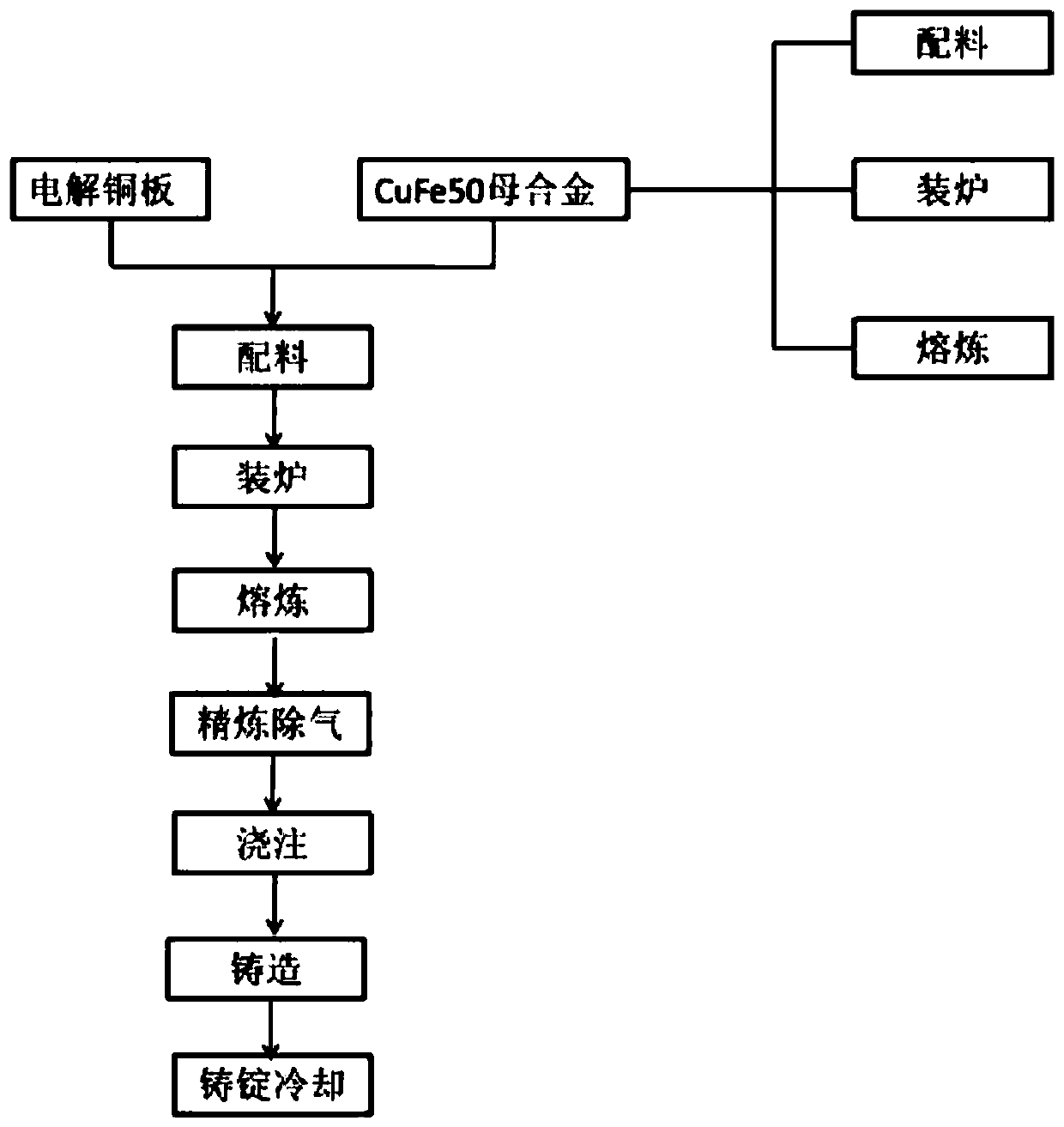
[0039] (1) Melting steps of CuFe50 master alloy:

[0040] The first step: batching and loading into the furnace, weighing Cu and Fe raw materials according to the ratio of content percentage of 1:1, mixing them evenly, putting them into a crucible and putting them in a vacuum melting furnace;

[0041] Step 2: Vacuum induction smelting, turn on the mechanical pump and the low vacuum baffle valve to evacuate, and when the P in the vacuum melting furnace is ≤0.08MPa, turn on the Roots pump; when the vacuum is evacuated to P≤4Pa, the power of the heating device will increase To 20KWKW, keep warm for 5min; the heating power of the heating device is raised to 40KW, and keep warm for 5min; ;When the pressure in the furnace rises to 0.08Mpa, stop charging with argon, increase the power to 65KW, and refine for 1min;

[0042] Step 3: Casting out of the furnace, reduce the power of the vacuum melting furnace to 35KW, keep it for 0.5 minutes and start pouring into the casting mold, turn ...

Embodiment 4-6

[0056] (1) Melting steps of CuFe50 master alloy:

[0057] The first step: batching and loading into the furnace, weighing Cu and Fe raw materials according to the ratio of content percentage of 1:1, mixing them evenly, putting them into a crucible and putting them in a vacuum melting furnace;

[0058] Step 2: Vacuum induction smelting, turn on the mechanical pump and the low vacuum baffle valve to evacuate, and when the P in the vacuum melting furnace is ≤0.08MPa, turn on the Roots pump; when the vacuum is evacuated to P≤4Pa, the power of the heating device will increase to 30KW, keep warm for 10min; the heating power of the heating device is raised to 50KW, and keep warm for 10min; Gas; when the pressure in the furnace rises to 0.08Mpa, stop charging with argon, raise the power to 75KW, and refine for 2 minutes;

[0059] Step 3: Casting out of the furnace, reduce the power of the vacuum melting furnace to 45KW, keep it for 0.5 minutes and start pouring into the casting mold,...


PUM


Abstract

The invention discloses a production process of a non-vacuum downwards-drawing continuous casting copper-iron alloy slab ingot. The production process mainly comprises the following steps of burdening, charging, smelting, refining degassing, pouring, casting and ingot casting, wherein the copper-iron alloy slab ingot is successfully prepared by using an electrolytic copper plate and a CuFe50 master alloy as smelting raw materials through a non-vacuum downwards-drawing continuous casting process, and compared with a traditional vacuum casting process, the equipment requirement is low; inert gasprotection is adopted in the casting process, appropriate measures such as iron content are adjusted, and the alloy composition and the oxygen content are effectively controlled; the process has theadvantages of being stable in process, simple and convenient to operate, low in casting production cost and capable of realizing industrial production of the copper-iron alloy slab ingot.

Description

technical field [0001] The invention relates to the technical field of metal smelting, in particular to a production process for non-vacuum down-drawing continuous casting copper-iron alloy slabs. Background technique [0002] As high-strength and high-conductivity copper-iron alloys are widely used in various industries, higher requirements are placed on the performance and manufacturing costs of such high-strength and high-conductivity copper-iron alloys. Copper-iron alloys exhibit unique and superior characteristics, such as electromagnetic wave shielding, Elasticity, conductivity, heat release, wear resistance, antibacterial properties, etc., and copper-iron alloys can be processed into various physical forms such as rods, cables, plates, films, powders, tubes, etc., and can be used in various industrial fields , has unsurpassed competitiveness and market prospects. [0003] However, judging from the copper-iron phase diagram, the two are almost completely immiscible a...

Claims


Application Information

Patent Timeline
Patent Type & Authority Applications(China)
IPC IPC(8): C22C9/00C22C1/03C22C1/06B22D11/00B22D11/115
CPCC22C9/00C22C1/03C22C1/06B22D11/004B22D11/115B22D11/112B22D11/113B22D11/117
Inventor 孙君鹏周斌王群郭创立杨红艳王文斌梁相博梁建斌张青队耿社虎武旭红
Owner SIRUI ADVANCED COPPER ALLOY CO LTD
Why Eureka
Try Eureka