

Self-locking cable clamp with unlocking mechanisms
A technology of unlocking mechanism and cable clamp, which is applied in the direction of winding connectors, etc., can solve problems such as unfavorable handling, maintenance and reuse, increased risk of high-altitude operations, cumbersome unlocking work, etc., and achieves simple structure, convenient unlocking, and energy saving resource effect
- Summary
- Abstract
- Description
- Claims
- Application Information
AI Technical Summary
Problems solved by technology
Method used
Image

Examples
Embodiment 1
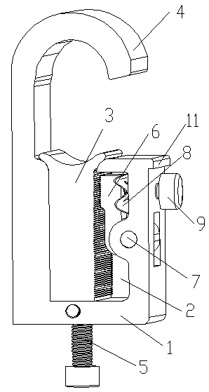
[0043] Such as figure 1 As shown, a self-locking cable clamp with an unlocking mechanism includes a connecting clamp, the connecting clamp includes a clamp body 1, a groove 2 is provided in the clamp body 1, and a groove 2 is embedded in the groove 2, which can be moved up and down. The movable chuck 3 is fixedly connected to the clamp body 1 with the static chuck 4 opposite to the clamping end of the movable chuck 3, and a bolt hole is provided on the opposite side of the clamp body 1 to the opening of the groove 2 , while an adjusting bolt 5 passes through the bolt hole and is fixedly connected to the clamp body 1, it is connected to the movable chuck 3, and one side of the movable chuck 3 connected to the wire clamp is provided with a downward check sawtooth. The anti-loosening and anti-reversing sawtooth block 6 is provided on the outer side of the anti-reverse sawtooth of the movable chuck 3, and the end of the anti-loosening and anti-reversal sawtooth block 6 close to th...
Embodiment 2
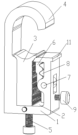
[0052] Such as figure 2 and Figure 11 As shown, on the basis of embodiment 1, this embodiment has made the following improvements:
[0053] The difference between this embodiment and Embodiment 1 lies in: the structure of the anti-loosening anti-reverse sawtooth block 6, the hinged part between it and the clamp body 1 and the setting part of the unlocking lever are as follows:
[0054] The anti-loosening and anti-reversing sawtooth block 6 is hinged with the clamp body 1 through a rotating shaft 7. The part where the anti-loosening and anti-reversing sawtooth block 6 is provided with the rotating shaft 7 divides the anti-loosening and anti-reversing sawtooth block 6 into two sections, which are respectively the upper section and the lower section, the anti-loose anti-reverse sawtooth block 6 is arranged on the side of the upper end of the upper part of the anti-loose anti-reverse sawtooth block 6 or the side of the lower end of the lower section, the unlocking lever 9 is a ...
Embodiment 3
[0057] On the basis of embodiment 1, this embodiment has been improved as follows:
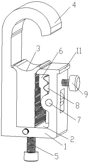
[0058] Such as image 3 and Figure 12 As shown, the difference between this embodiment and Embodiment 1 is: the structure of the anti-loosening anti-backward sawtooth block 6 is as follows:
[0059] The anti-loosening and anti-reversing sawtooth block 6 is hinged with the clamp body 1 through a rotating shaft 7. The part where the anti-loosening and anti-reversing sawtooth block 6 is provided with the rotating shaft 7 divides the anti-loosening and anti-reversing sawtooth block 6 into two sections, which are respectively the upper section and the lower section, the anti-loose anti-reverse sawtooth block 6 is arranged on the upper or lower side of the anti-loose anti-reverse sawtooth block 6, the unlocking lever 9 is a pull bar, and the side of the clamp body 1 is provided with a pull bar Through the through hole, the pull rod passes through the through hole, the compression spring is fixedl...
PUM
 Abstract
Description
Claims
Application Information