Lighting device and method for operating the lighting device

a lighting device and a technology for lighting devices, applied in the direction of electroluminescent light sources, electronic switching, pulse techniques, etc., can solve the problems of not being able to design a lighting device by, and the construction of these lighting devices is not very narrow in the vertical direction, so as to facilitate the finding of light-emitting elements

Active Publication Date: 2019-08-06
HELLA KG HUECK & CO
View PDF24 Cites 0 Cited by
  • Summary
  • Abstract
  • Description
  • Claims
  • Application Information

AI Technical Summary

Benefits of technology

[0005]It is the object of the present invention, therefore, to create a lighting device which is constructed in a simple and especially flat manner and, nevertheless, is individually controllable. It is also the object of the present invention to create a method for operating a lighting device which can be executed in a simple manner and, nevertheless, allows individual controllability.

Problems solved by technology

However, the construction of these lighting devices is not very narrow in the vertical direction.
However, it is not possible to design a lighting device by this means, especially for the rear area or the front area of the vehicle passenger compartment.
If all light-emitting elements are switched off, this would thus result in switching-on.

Method used


Image

  • Lighting device and method for operating the lighting device
  • Lighting device and method for operating the lighting device
  • Lighting device and method for operating the lighting device

Examples


Embodiment Construction

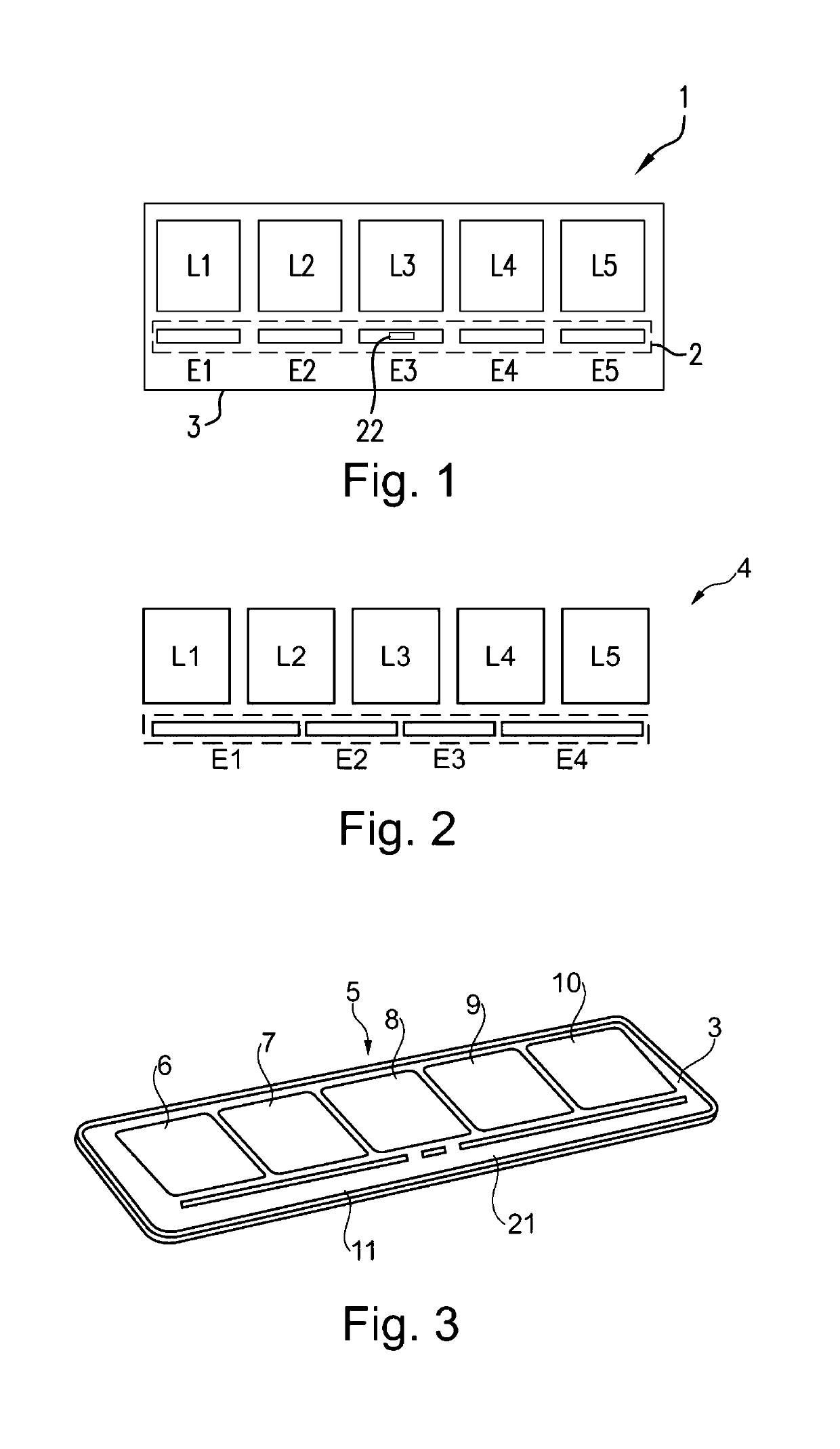
[0065]FIG. 1 shows a lighting device 1 having a first number N1 of light-emitting elements L1, L2, L3, L4, L5, wherein also a second number N2 of control elements E1, E2, E3, E4, E5 advantageously operating contactlessly is provided.

[0066]The control elements E1 to E5 are used for switching the light-emitting elements L1 to L5 on or off and / or controlling their brightness. In this context, a light-emitting element can be driven continuously by PWM modulation in its brightness or it can be switched on or off completely.

[0067]The light-emitting elements L1 to L5 are represented as two-dimensional, for example rectangular or square light-emitting elements which are arranged next to one another in one row. The control elements E1 to E5 are represented as narrow rectangular elements which are also arranged next to one another flush in one row with one another. The light-emitting elements L1 to L5 are in this case arranged in one row, the row of light-emitting elements being arranged in p...


PUM


Abstract

The invention relates to a lighting device having a first number of light-emitting elements and having a second number of control elements, operating contactlessly, for controlling the light-emitting elements such as especially for switching the light-emitting elements on or off and / or for controlling their brightness, the second number being less than or equal to the first number, the light-emitting elements being controlled contactlessly by a movement of at least one hand of a user over two or more control elements. The invention also relates to a relevant method.

Description

CROSS-REFERENCE TO RELATED PATENT APPLICATIONS[0001]This application is based upon and claims the benefit of priority from prior German Patent Application No. 10 2013 200 512.1, filed Jan. 15, 2013, the entire contents of which are incorporated herein by reference in their entirety.TECHNICAL FIELD[0002]The invention relates to a lighting device and a method for operating a lighting device.PRIOR ART[0003]In the prior art, lighting devices are known which are applied in the vehicle passenger compartment. In this context, light-emitting elements are used which are in each case switched on by means of mechanical switches and locally generate a light for an operator or passenger. However, the construction of these lighting devices is not very narrow in the vertical direction.[0004]Lighting devices have also become known which comprise a proximity sensor as is disclosed in DE 10 2005 005 411 A1. This printed document discloses an control element which is illuminated when approached with a...

Claims


Application Information

Patent Timeline
Patent Type & Authority Patents(United States)
IPC IPC(8): H05B33/08H05B37/02H03K17/96H05B44/00
CPCH05B37/0227H05B37/0245H05B33/0863H03K17/962H05B47/175H05B47/115Y02B20/40
Inventor HEINRICH, JURGEN
Owner HELLA KG HUECK & CO
Why Eureka
Try Eureka