Robot controller and robot control method

a robot controller and robot technology, applied in the direction of programmed control, manipulators, instruments, etc., can solve the problem that the robot controller cannot calculate the power generated at the tool center point of the robo

Active Publication Date: 2019-08-13
YASKAWA DENKI KK
View PDF30 Cites 0 Cited by
  • Summary
  • Abstract
  • Description
  • Claims
  • Application Information

AI Technical Summary

Benefits of technology

[0010]Therefore, the present disclosure has been made in consideration of the above problem, and an object of the present disclosure is to provide a robot controller and a robot control method, capable of ensuring that power in an operation direction generated at the tool center point of a robot is a designated value or less, even in a case where the robot has been in proximity to a singular configuration.

Problems solved by technology

However, the robot controller cannot calculate the power generated at the tool center point of the robot in a case where the robot has been in a singular configuration (namely, at a singularity of the robot).
As a result, there is a problem that ensuring that the power generated at the tool center point is the designated value or less cannot be made.

Method used


Image

  • Robot controller and robot control method
  • Robot controller and robot control method
  • Robot controller and robot control method

Examples


Embodiment Construction

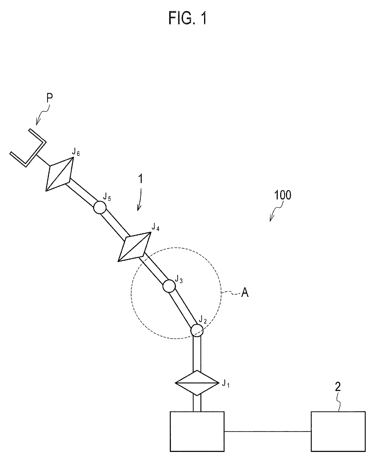
[0019]One embodiment will be described below with reference to FIGS. 1 to 5. As illustrated in FIG. 1, a robot system 100 according to the present embodiment includes a robot 1 and a robot controller 2 configured to control the robot 1.

[0020]According to the present embodiment, the robot 1 includes an arm having a plurality of joints J1 to J6. The plurality of joints J1 to J6 is configured to be capable of rotating around rotation axes thereof (not illustrated).

[0021]Note that, according to the present embodiment, the robot 1 is premised on performing work in cooperation with a human so that the robot controller 2 controls power generated at tool center point P of the robot 1, to be a designated value (e.g., 150 N) or less, as described above. Here, according to the present embodiment, the tool center point P of the robot 1 is a representative point of a tool fitted to a leading end of the arm of the robot 1.

[0022]According to the present embodiment, as illustrated in FIG. 1, a mult...


PUM


Abstract

A robot controller (2) configured to control a robot (1) including a plurality of joints (J1-J6) each rotatable around a rotation axis, the robot controller (2) including: an acquisition unit (21) configured to acquire a rotation angle of each of the plurality of joints (J1-J6); a determination unit (22) configured to determine whether or not the robot (1) has been in proximity to a singular configuration, based on the rotation angle of each of the plurality of joints (J1-J6); and a control unit (23) configured to control the plurality of joints (J1-J6) to be rotated not to rotate simultaneously, when the determination unit (22) determines that the robot (1) has been in proximity to the singular configuration.

Description

INCORPORATION BY REFERENCE[0001]The present disclosure contains subject matter related to that disclosed in Japanese Priority Patent Application JP 2016-054031 filed in the Japan Patent Office on Mar. 17, 2016, the entire contents of which are hereby incorporated by reference.BACKGROUND[0002]Technical Field[0003]The present disclosure relates to a robot controller and a robot control method.[0004]Related Art[0005]Conventionally, a technique of controlling a robot that performs work in cooperation with a human, has been known (refer to Japanese Patent Application National Publication (Laid-Open) No. 2015-511544).[0006]In requirements for a robot that performs work in cooperation with a human, based on ISO 10218-1, ensuring that power generated at the tool center point (TCP) of the robot is a designated value (e.g., 150 N) or less, is required.[0007]Here, a robot controller that controls the robot, calculates the power generated at the tool center point of the robot, based on torque a...

Claims


Application Information

Patent Timeline
Patent Type & Authority Patents(United States)
IPC IPC(8): B25J9/16
CPCB25J9/1651B25J9/161B25J9/1694B25J9/1607G05B2219/40333B25J9/1602
Inventor SHIKINA, TAKUNISHIMURANAKAMURA, TAMIO
Owner YASKAWA DENKI KK
Why Eureka
Try Eureka