Wire

a technology of wires and strands, applied in the field of wires, can solve the problems of increased cost and impaired and achieve the effect of improving the flexibility of stranded conductors and reducing the cost of production

Active Publication Date: 2019-08-13
AUTONETWORKS TECH LTD +2
View PDF11 Cites 0 Cited by
  • Summary
  • Abstract
  • Description
  • Claims
  • Application Information

AI Technical Summary

Benefits of technology

[0006]The wire may have a plurality of bent portions and a straight portion linearly connecting between the respective bent portions. In this configuration, the sum of section lengths of the respective bent portions and the sum of section lengths of the straight portions are both an integer multiple of the twist pitch According to this configuration, even in the wire including the straight portion in an intermediate part, total route lengths of the respective strand conductors in the plurality of bent portions are equal. Further, the twist pitch is maintained in the straight portion. Therefore, the flexibility of the wire is not impaired and, even if an end of the wire is fixed, the bent portion does not bulge.
[0010]According to the wire disclosed in this specification, it is possible to prevent an end part of the wire from becoming irregular and to prevent the conductor strands from bulging in the bent portion even if the wire is a stranded wire and includes the bent portion.

Problems solved by technology

If these shape abnormalities are corrected, the inherent flexibility of the stranded conductor is impaired.
However, in the configuration of Japanese Unexamined Patent Publication No. 2014-143217, cost may increase since a dedicated wire needs to be prepared to avoid shape abnormalities of a bent portion of the wire.

Method used


Image

  • Wire
  • Wire
  • Wire

Examples


first embodiment

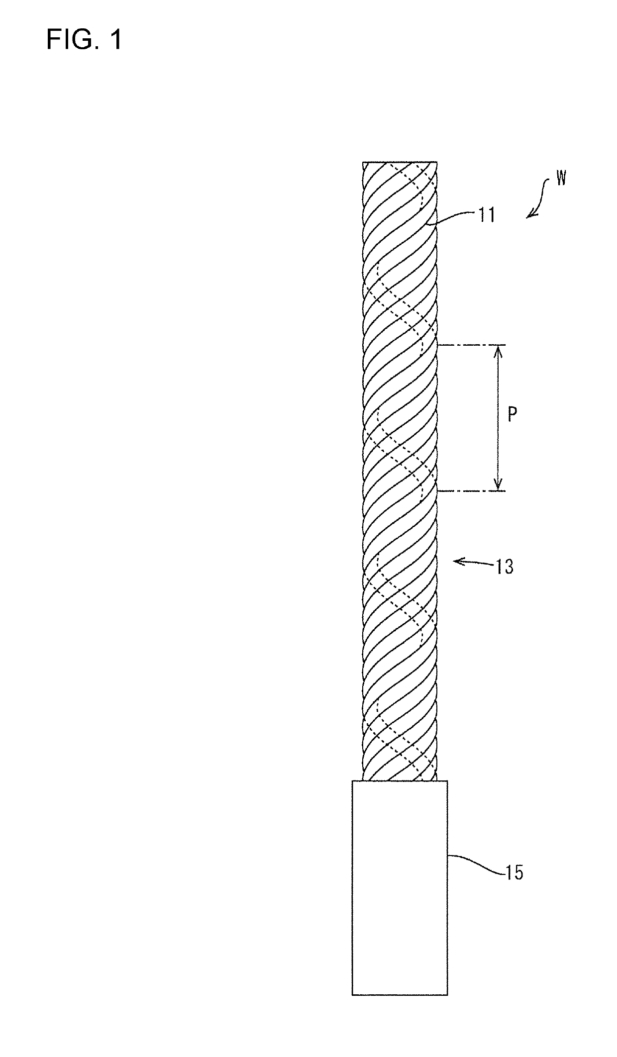
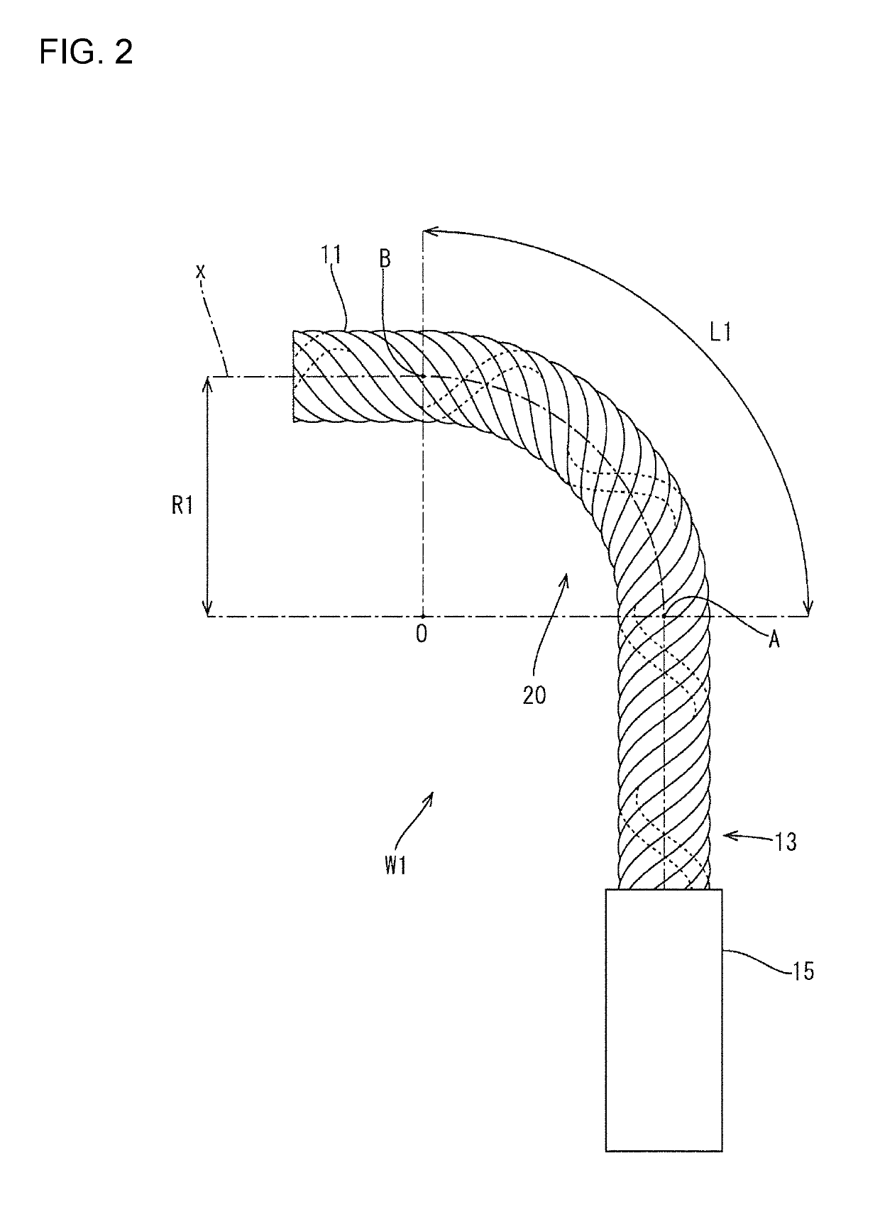
[0022]A wire W1 of this embodiment is described with respect to FIGS. 2 and 3. In this embodiment, as shown in FIG. 2, the wire W is one type of the wire shown in FIG. 1 and has a bent portion 20 bent at a radius of curvature R1. The bent portion 20 is provided in a part where a core 13 formed by twisting strand conductors 11 at a twist pitch P1 is exposed, and is bent such that a line along the wire W1 between a point A (bend start point) and a point B (bend end point) forms an arc of approximately 90°. Note that the radius of curvature R1 is a distance from a center axis x of the core 13 to a center of curvature O. Further, a curvature K1 serving as an index of a bent state is defined as an inverse of the radius of curvature (K1=1 / R1). That is, the wire W1 has the bent portion 20 bent with the curvature K1.

[0023]A section length L1 of the bent portion 20 indicates a length of a section where the wire W1 is bent (length from the point A to the point B) as shown in FIG. 2. More spec...

second embodiment

[0029]A wire W2 with a bent portion 120 having a different shape is described using FIG. 4. Note that the same components as in the first embodiment are denoted by the same reference signs and are not described. Further, each strand conductor 11 is not shown to simplify the drawing.

[0030]In this embodiment, as shown in FIG. 4, the wire W2 as one type of the wire shown in FIG. 1 includes the bent portion 120 having a bent shape with a curvature K2. The bent portion 120 is provided in a part where a core 13 formed by twisting strand conductors 11 at a twist pitch P2 is exposed, and bent such that a line along the wire W2 between a start point and an end point forms an arc of approximately 270°.

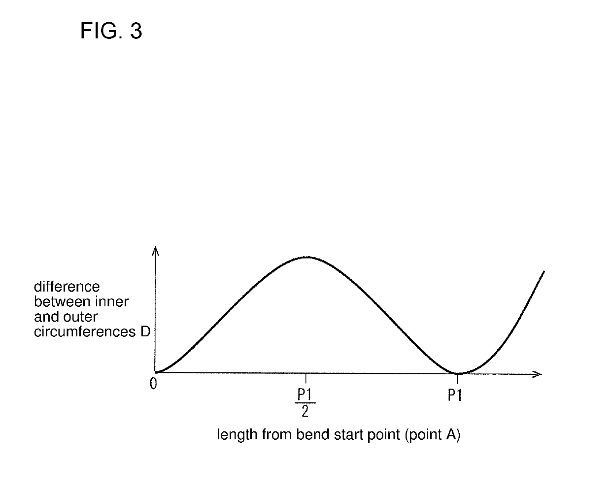
[0031]As in the first embodiment, when a section length L2 of the bent portion 120 is an integer multiple of the twist pitch P2, a difference D between inner and outer circumferences of the bent portion 120 is 0. That is, when the section length L2 of the bent portion 120 is an integer multiple ...

third embodiment

[0033]A wire W3 with bent portions 220 having a different shape is described using FIG. 5. Note that the same components as in the first embodiment are denoted by the same reference signs and are not described. Further, each strand conductor 11 is not shown to simplify the drawing.

[0034]In this embodiment, as shown in FIG. 5, the wire W3 as one type of the wire shown in FIG. 1 includes two bent portions 220 having a bent shape with a curvature K3 and a straight portion 230 linearly connecting between the respective bent portions 220. The bent portions 220 and the straight portion 230 are provided in a part where a core 13 formed by twisting strand conductors 11 at a twist pitch P3 is exposed. Each bent portion 220 is bent with the same curvature K3 such that a line along the wire W3 between a bend start point and a bend end point of the bent portion 220 forms an arc of approximately 90°. The straight portion 230 is provided between the respective bent portions 220 and the respective...


PUM

PropertyMeasurementUnit
angleaaaaaaaaaa
section lengthaaaaaaaaaa
section lengthsaaaaaaaaaa

Abstract

A wire W1 is a wire W1 in which a plurality of strand conductors 11 are twisted at a predetermined twist pitch P1 and which includes a bent portion 20 having a bent shape with a curvature K. A section length L1 of the bent portion 20 is an integer multiple of the twist pitch P1.

Description

BACKGROUNDField of the Invention[0001]This specification relates to a wire.Description of the Related Art[0002]Conventional coated wires used for wiring of vehicles, electric and electronic devices and the like have a conductor coated with an insulator. A conductor of this wire generally is configured by twisting a plurality of metal strands. If a stranded conductor formed by twisting the strands in this way is bent, a length differs for each of the strands located on an inner peripheral side and an outer peripheral side in a bent portion. Thus, if an end of the stranded conductor is not fixed, end parts of respective strands 1a of a wire 1 are irregular, as shown in FIG. 8. Further, if the end of the stranded conductor is fixed, such as by a terminal 6, a bent portion 7 of a wire 5 bulges, as shown in FIG. 9. If these shape abnormalities are corrected, the inherent flexibility of the stranded conductor is impaired.[0003]Japanese Unexamined Patent Publication No. 2014-143217 attempt...

Claims


Application Information

Patent Timeline
Patent Type & Authority Patents(United States)
IPC IPC(8): H01B5/08H01B7/04H01B7/00H01B13/02
CPCH01B7/04H01B13/02H01B7/0009
Inventor SAKAGUCHI, KIYOKAZU
Owner AUTONETWORKS TECH LTD
Why Eureka
Try Eureka