Dispersion-optimized bend-insensitive optical fiber

A bend-insensitive, optical fiber technology, applied in clad optical fibers, multi-layer core/clad optical fibers, light guides, etc., can solve problems such as difficulty in meeting the requirements of bending loss, avoid excessive bending loss, and optimize the dispersion coefficient. Effect

Active Publication Date: 2021-11-09
YANGTZE OPTICAL FIBRE & CABLE CO LTD
View PDF12 Cites 0 Cited by
  • Summary
  • Abstract
  • Description
  • Claims
  • Application Information

AI Technical Summary

Problems solved by technology

[0004] Bend-insensitive optical fibers generally have a depressed cladding, and optimized bend-insensitive single-mode optical fiber patent documents CN110780379B, CN110749953A, CN103257397B, and CN102200610B use a depressed cladding while also setting a raised cladding. However, from the example data, it is difficult to meet the bending loss requirements of G.657.A2 and G.657.B3 under small bending radii for the design of such a dispersion-optimized single-mode fiber convex cladding

Method used


Image

  • Dispersion-optimized bend-insensitive optical fiber
  • Dispersion-optimized bend-insensitive optical fiber
  • Dispersion-optimized bend-insensitive optical fiber

Examples


Embodiment 1-1~10

[0055] Embodiment 1-1~10 G657A2 standard optical fiber

[0056] The geometric dimensions and refractive index parameters adopted by the G657A2 standard optical fiber are shown in the table below;

[0057]

[0058]

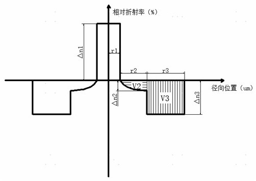
[0059] The relative refractive index difference change curve of the transitional depressed cladding can be expressed as:

[0060]

[0061] in is the distance from a point in the transitional depressed cladding to the boundary of the core cladding, is the distribution index, is the refractive index of the core layer relative to pure silica, that is, its relative refractive index difference, is the refractive index of the depressed cladding relative to pure silica, that is, its relative refractive index difference, is the transitional sag cladding width.

[0062] After testing, the attenuation of the G657A2 standard optical fiber provided in Examples 1-1~10 at a wavelength of 1310nm is less than or equal to 0.330dB / km; the attenuation at a waveleng...

Embodiment 2-1~10

[0072] Embodiment 2-1~10 G657B3 standard optical fiber

[0073] The geometric dimensions and refractive index parameters adopted by the G657B3 standard optical fiber are shown in the table below;

[0074]

[0075]

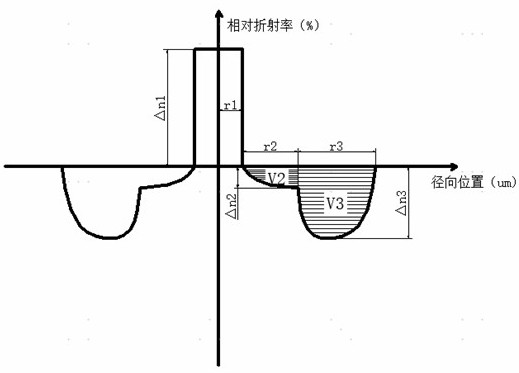
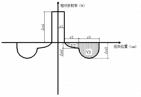
[0076] The refractive index variation curve of the transitional depressed cladding can be expressed as:

[0077]

[0078] in is the distance from a point in the transitional depressed cladding to the boundary of the core cladding, is the distribution index, is the refractive index of the core layer relative to pure silica, is the refractive index of the depressed cladding relative to pure silica, is the transitional sag cladding width.

[0079] After testing, the attenuation of the G657B3 standard optical fiber provided in Examples 2-1~10 at a wavelength of 1310nm is less than or equal to 0.330dB / km; the attenuation at a wavelength of 1383nm is less than or equal to 0.284 dB / km; Less than or equal to 0.190dB / km; attenuation at a wavelength of 16...


PUM

PropertyMeasurementUnit
radiusaaaaaaaaaa
widthaaaaaaaaaa
widthaaaaaaaaaa

Abstract

The invention discloses a dispersion-optimized bending-insensitive optical fiber. A transition sunken cladding is arranged between a core layer and a sunken cladding, and the relative refractive index difference of the transition sunken cladding continuously changes from 0% to the relative refractive index difference of a junction point of the sunken cladding from inside to outside. According to the invention, the waveguide dispersion and macro-bending performance are balanced and optimized by adopting the double sunken claddings, so that the dispersion coefficient of the optical fiber is reduced on the premise that the bending performance of the optical fiber is not influenced; wherein the refractive index of the transition sunken cladding between the core layer and the sunken cladding changes continuously, so that waveguide dispersion caused by the refractive index difference between the core layer and the cladding in the waveguide structure is reduced, the refractive index distribution and width of the transition sunken cladding are limited, the dispersion coefficient is optimized, and the problem that the bending loss is too large under the small bending radius due to the convex cladding is avoided.

Description

technical field [0001] The invention belongs to the field of optical fiber communication, and more specifically relates to a dispersion-optimized bend-insensitive optical fiber. Background technique [0002] Dispersion is an important transmission characteristic of optical fiber. Dispersion is a physical effect in which different frequency or mode components in light waves travel at different speeds and produce different time delays. With the continuous increase of the optical fiber transmission distance, the broadening of the optical pulse caused by dispersion causes the front and rear pulses to overlap each other, causing inter-symbol crosstalk of digital signals, resulting in an increase in the bit error rate. There are mainly two kinds of dispersion in single-mode optical fiber: material dispersion and waveguide dispersion. Material dispersion is the dispersion characteristic caused by the signal pulse broadening caused by the group refractive index of the material chan...

Claims


Application Information

Patent Timeline
Patent Type & Authority Applications(China)
IPC IPC(8): G02B6/036
CPCG02B6/03644G02B6/03694
Inventor 雷汉林王瑞春顾立新朱继红刘善沛黄利伟曹蓓蓓吴俊
Owner YANGTZE OPTICAL FIBRE & CABLE CO LTD
Why Eureka
Try Eureka