Sinus balloon catheter with adjustable bending angle and balloon position

a balloon catheter and adjustable technology, applied in the field of balloon catheters, can solve the problems of severe inconvenience to the daily life of patients, and the bending angle of the balloon catheter cannot be adjusted,

Active Publication Date: 2019-08-20
GIL MEDICAL CENT +1
View PDF15 Cites 0 Cited by
  • Summary
  • Abstract
  • Description
  • Claims
  • Application Information

AI Technical Summary

Benefits of technology

[0009]In particular, the present invention provides a sinus balloon catheter that may be inserted according to the sinus structures that are different for the patients by freely adjusting a bending angle of the balloon catheter and a position of a balloon.

Problems solved by technology

It is often called sinus infection, and causes severe inconvenience to the daily life of the patient.
Korean Patent Application Publication No. 10-2012-0012796 discloses a technology of inclining catheter at an angle of 0 to 180 degrees with respect to a shaft through a flexible distal tip, but the catheter is inclined simply due to the flexible distal tip and a bending angle of the balloon catheter cannot be adjusted.

Method used


Image

  • Sinus balloon catheter with adjustable bending angle and balloon position
  • Sinus balloon catheter with adjustable bending angle and balloon position
  • Sinus balloon catheter with adjustable bending angle and balloon position

Examples


first embodiment

1. First Embodiment

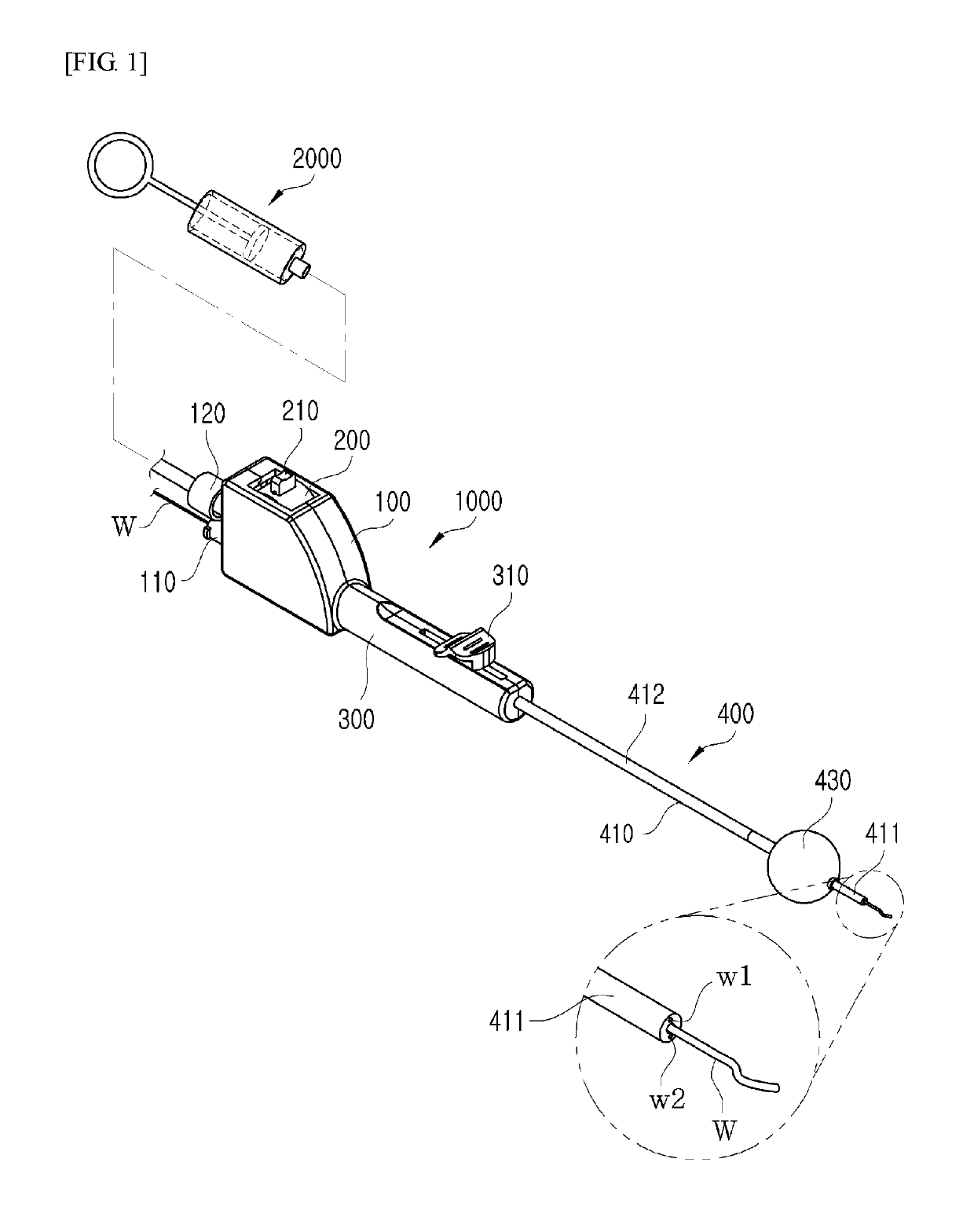
[0034]First, the sinus balloon catheter according to a first embodiment of the present invention will be described with reference to FIGS. 1 to 3.

[0035]Referring to FIG. 1, the sinus balloon catheter according to the first embodiment of the present invention includes a balloon catheter body 1000 and a fluid injection unit 2000.

[0036]The balloon catheter body 1000 is a part that is inserted into a sinus to perform a treatment. Referring to FIG. 1, the balloon catheter body 1000 includes a body unit 100, a bending angle adjusting unit 200, an extension part 300, and a guide unit 400.

[0037]The body unit 100 is a part, to which the bending angle adjusting unit 200 for adjusting a bending angle of the balloon catheter is mounted. The body unit 100 includes a guide wire insertion part 110 and a fluid injection part 120.

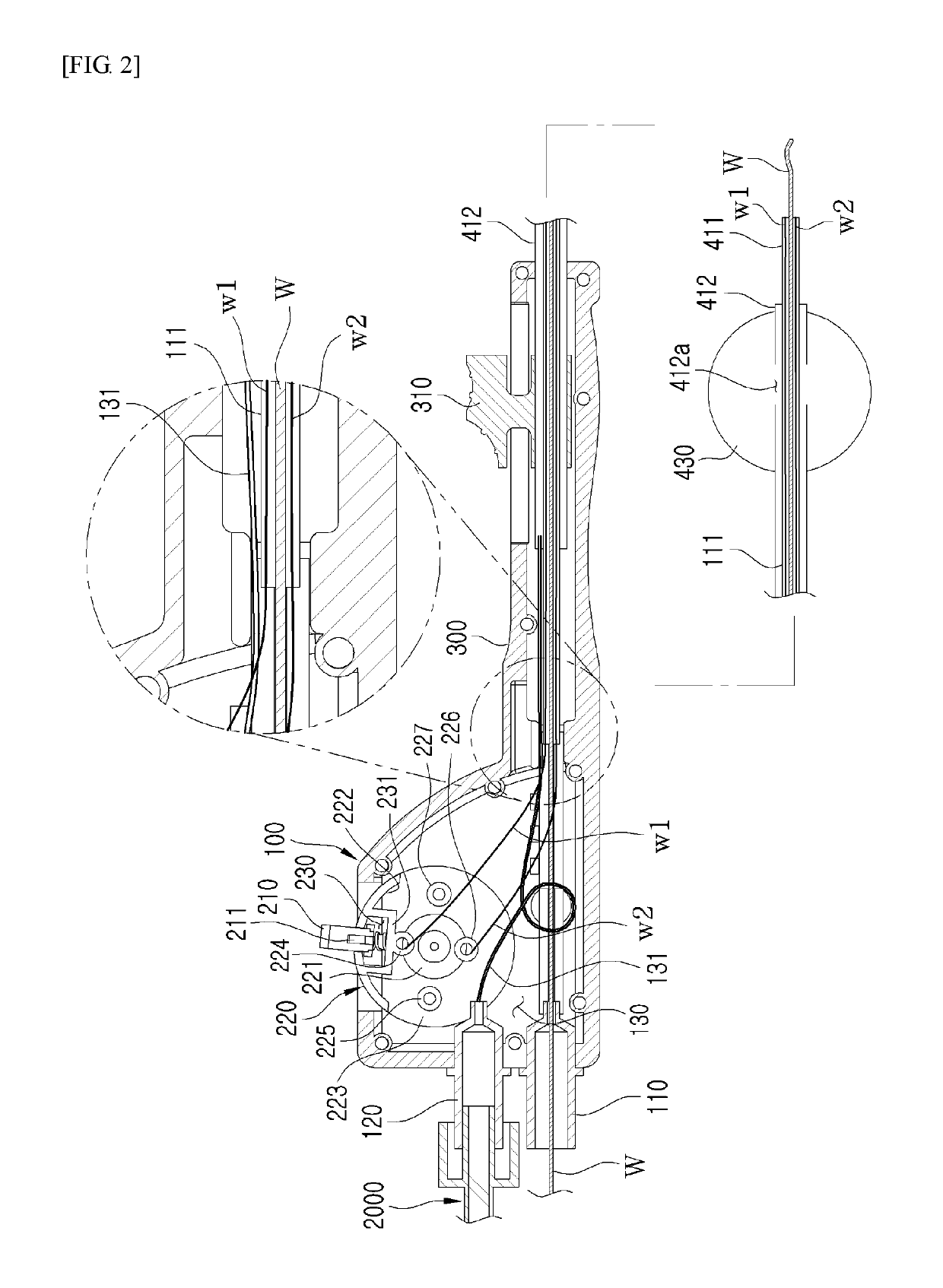
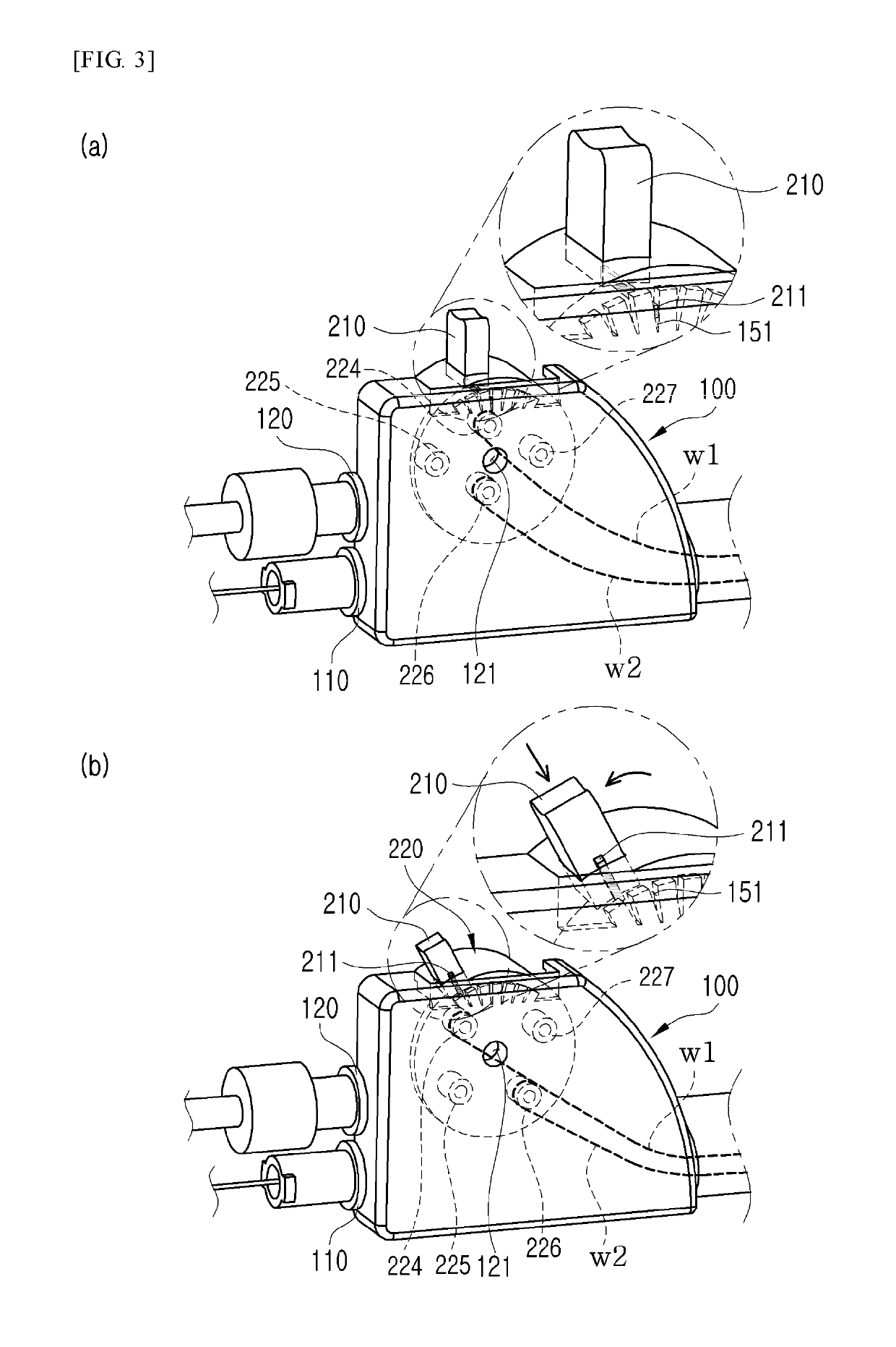
[0038]A plurality of fixing grooves 141 for fixing a bending angle of the balloon catheter are formed on an upper surface of the body unit 100. A fixing ...

second embodiment

2. Second Embodiment

[0063]Hereinafter, the sinus balloon catheter according to a second embodiment of the present invention will be described with reference to FIGS. 4 to 5.

[0064]As in the first embodiment, a bending angle of the tip end of the balloon catheter is adjusted through manipulation of the bending angle adjusting unit 200, and the position of the balloon 430 is changed through manipulation of the balloon position adjusting lever 310.

[0065]However, as a configuration of fixing the bending angle of the balloon catheter is different from that of the first embodiment, a description of the same parts will be omitted and only parts that are different from those of the first embodiment will be described in detail.

[0066]Referring to FIG. 4, a first magnetic groove 240, into which a first magnetic body having a first polarity is inserted, is formed on a side surface 223 of the rotary plate 220. A plurality of second magnetic grooves 141, 142, 143, and 144, into which a second magn...


PUM


Abstract

Disclosed is a sinus balloon catheter. The sinus balloon catheter includes a body unit, a bending angle adjusting unit that includes a bending angle adjusting lever and a rotary plate, and a guide unit that includes a balloon, and has a pair of bending angle adjusting wires therein. The guide unit includes a first guide body, and a second guide body that is slidably provided in the first guide body, the balloon is provided on the second guide body, the rotary plate is connected to any one of the pair of bending angle adjusting wires to be rotated, and the other bending angle adjusting wire is maintained within the guide unit, and the guide unit is inserted into any one of a sphenoidal sinus, a frontal sinus, and a maxillary sinus.

Description

CROSS-REFERENCE TO RELATED APPLICATION[0001]This application claims priority from and the benefit under 35 U.S.C. § 119(a) of Korean Patent Application No. 10-2016-0158375, filed on Nov. 25, 2016, which is hereby incorporated by reference for all purposes as if fully set forth herein.BACKGROUND OF THE INVENTION1. Field of the Invention[0002]The present invention relates to a balloon catheter, and more particularly, to a balloon catheter in which a bending angle of a tip end thereof and a position of a balloon may be freely adjusted.2. Description of the Prior Art[0003]Sinusitis is a disease by which secretion of a sinus cannot be easily discharged due to an abnormality of the sinus so that germ infection and inflammation are caused, a mucous membrane is swollen, and an entrance of the sinus is narrowed. It is often called sinus infection, and causes severe inconvenience to the daily life of the patient.[0004]A surgical procedure method using a balloon catheter as a method for treati...

Claims


Application Information

Patent Timeline
Patent Type & Authority Patents(United States)
IPC IPC(8): A61M29/02A61M25/10A61M25/01A61B17/24
CPCA61M29/02A61M25/0136A61M25/10182A61M2029/025A61B17/24A61M25/0147A61M25/1018A61M25/0074A61M2210/0681
Inventor KIM, SEONTAECHUN, HANYONGLEE, DONGHYUKSONG, SOOHWA
Owner GIL MEDICAL CENT
Why Eureka
Try Eureka