Ultrasound diagnostic apparatus and ultrasound probe

a diagnostic apparatus and ultrasound technology, applied in diagnostics, ultrasonic/sonic/infrasonic data transmission, medical science, etc., can solve the problems of malfunction, setting, and inability to execute proper ultrasound probe control of ultrasound diagnostic apparatus,

Active Publication Date: 2019-08-27
CANON MEDICAL SYST COPRPORATION
View PDF13 Cites 156 Cited by
  • Summary
  • Abstract
  • Description
  • Claims
  • Application Information

AI Technical Summary

Problems solved by technology

If, however, a probe whose operation is not guaranteed (e.g., a probe from another maker or a pirated probe to be referred to as an unguaranteed probe hereinafter) is erroneously connected to the main body of the ultrasound diagnostic apparatus, the ultrasound diagnostic apparatus erroneously detects the unguaranteed probe.
This makes i

Method used


Image

  • Ultrasound diagnostic apparatus and ultrasound probe
  • Ultrasound diagnostic apparatus and ultrasound probe
  • Ultrasound diagnostic apparatus and ultrasound probe

Examples


first embodiment

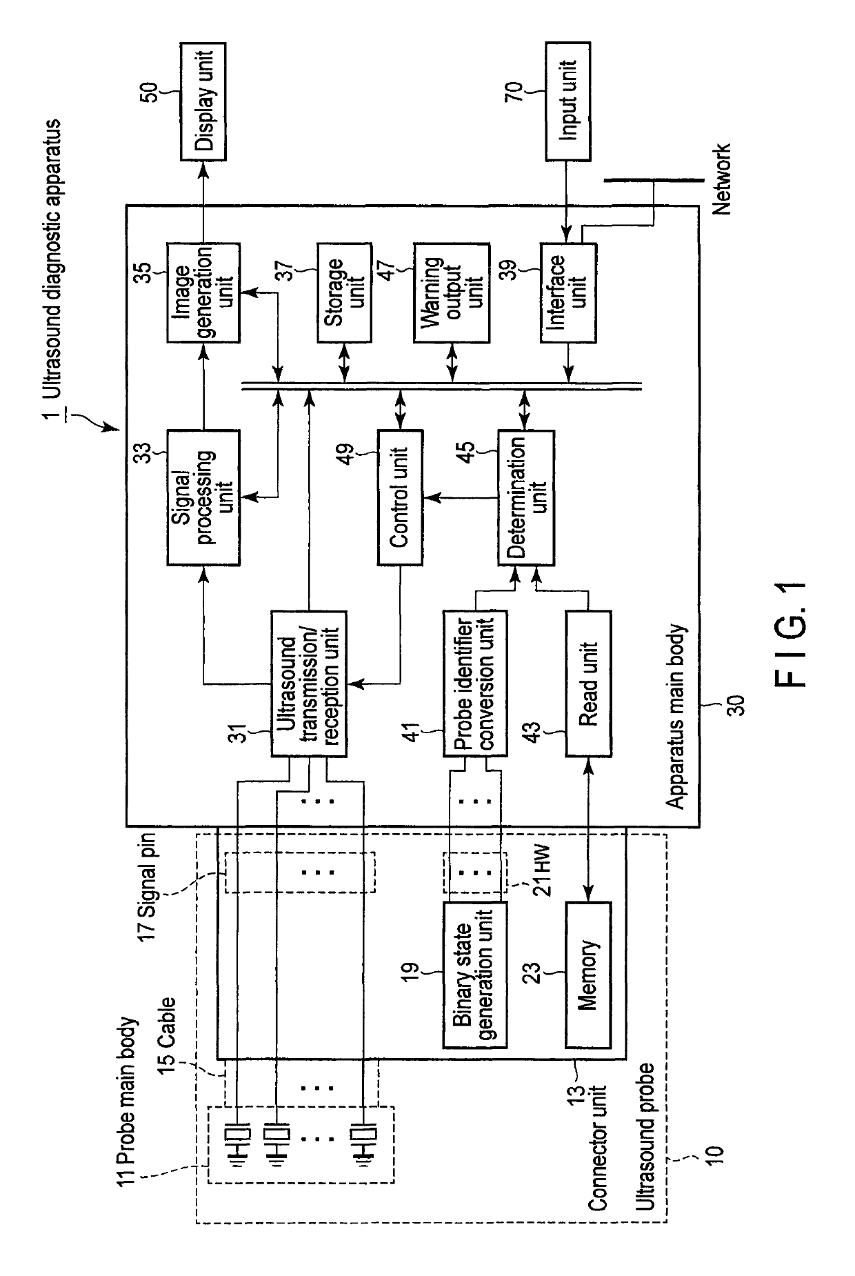
[0024]FIG. 1 is a block diagram showing an example of the arrangement of an ultrasound diagnostic apparatus according to the first embodiment. As shown in FIG. 1, an ultrasound diagnostic apparatus 1 includes an ultrasound probe 10, an apparatus main body 30, a display unit 50, and an input unit 70 which is connected to the apparatus main body 30 to input various types of instructions, commands, and information from the operator to the apparatus main body 30. A biological signal measurement unit (not shown) typified by an electrocardiograph, phonocardiograph, sphygmograph, or respiration sensor and a network may be connected to the ultrasound diagnostic apparatus 1 via an interface unit 39 to be described later.

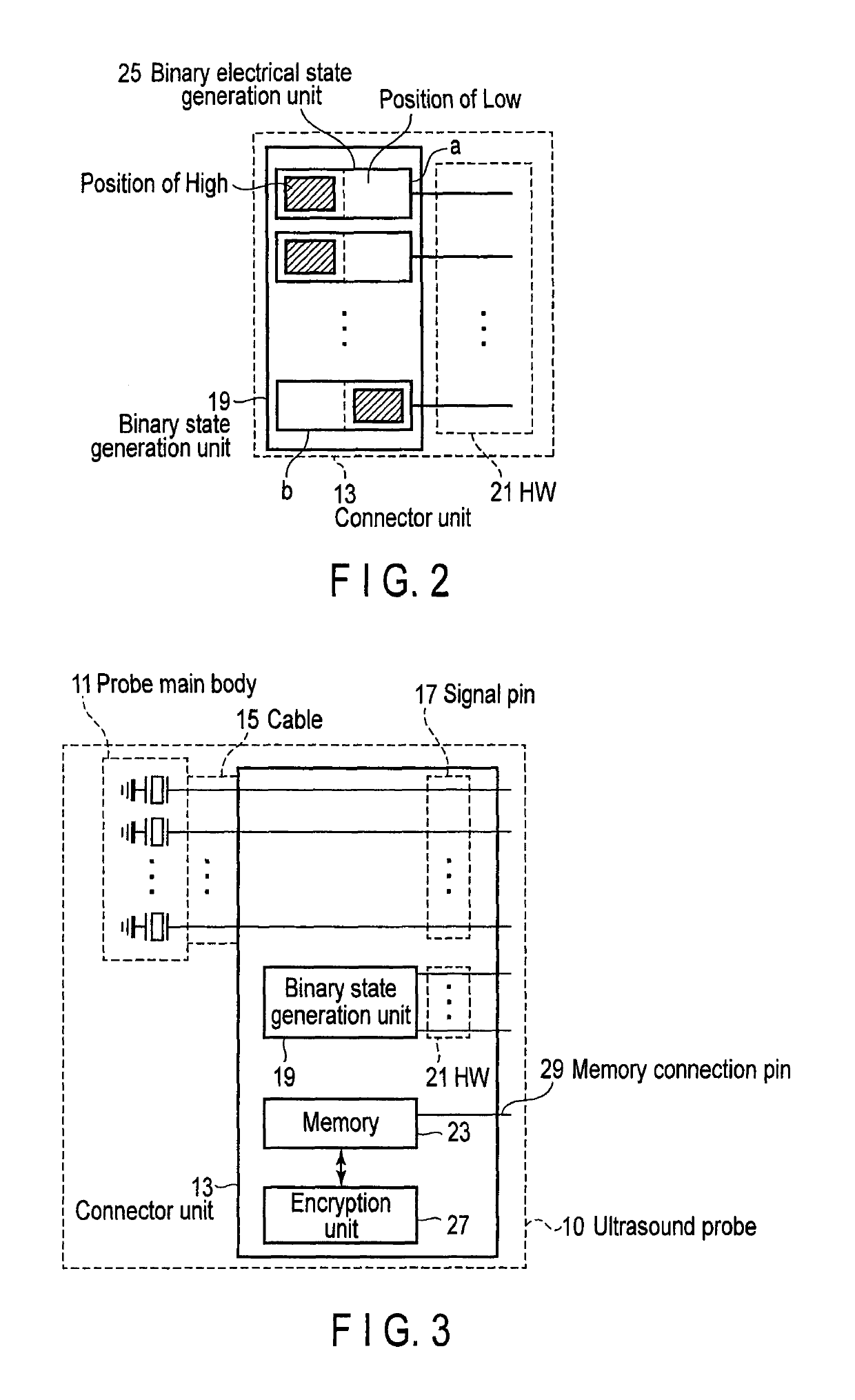
[0025]The ultrasound probe 10 includes a probe main body 11, a connector unit 13 connected to the apparatus main body 30 of the ultrasound diagnostic apparatus 1, and a cable 15 which electrically connects the probe main body 11 to the connector unit 13.

[0026]The probe main b...

second embodiment

[0077]The second embodiment differs from the first embodiment in that it is configured to determine consistency between the probe identification information stored in a memory 23 and the probe identification information list stored in an external storage medium or server.

[0078]FIG. 5 is a block diagram showing an example of the arrangement of an ultrasound diagnostic apparatus 1 according to the second embodiment. As shown in FIG. 5, an apparatus main body 30 includes a decryption unit 44. In addition, as shown in FIG. 5, an interface unit 39 is connected to a server 60 via a network. Note that an external storage medium 65 may be connected to the interface unit 39, as shown in FIG. 5.

[0079]The server 60 or external storage medium 65 stores a probe identification information list encrypted by a predetermined method. The probe identification information list is a list of probe identification information concerning each of a plurality of different types of ultrasound probes.

[0080]The ...

third embodiment

[0087]The third embodiment differs from the first and second embodiments in that it is configured to determine consistency between the probe ID generated based on electrical states and probe identification information associated with a return signal.

[0088]FIG. 7 is a block diagram showing an example of the arrangement of an ultrasound diagnostic apparatus 1 according to the third embodiment. As shown in FIG. 7, a connector unit 13 further includes a return signal generation unit 20. An apparatus main body 30 further includes a signal transmission / reception unit 46.

[0089]When the connector unit 13 of an ultrasound probe 10 is connected to the apparatus main body 30, the signal transmission / reception unit 46 generates a predetermined transmission signal to be transmitted to the return signal generation unit 20 (to be described later). The signal transmission / reception unit 46 transmits the generated predetermined transmission signal. The signal transmission / reception unit 46 receives ...


PUM


Abstract

An ultrasound diagnostic apparatus includes an ultrasound probe with transducers, memory storing probe identification information and binary state generation unit generating a binary electrical state corresponding to a probe identifier, probe identifier conversion unit converting the electrical state into the probe identifier, read unit reading the probe identification information from the memory, determination unit determining consistency between the probe identifier after conversion and the probe identification information read from the memory, and warning output unit outputting a predetermined warning if the probe identifier is inconsistent with the probe identification information.

Description

CROSS-REFERENCE TO RELATED APPLICATIONS[0001]This application is a Continuation application of PCT Application No. PCT / JP2013 / 067246, filed Jun. 24, 2013 and based upon and claims the benefit of priority from the Japanese Patent Application No. 2012-175203, filed Aug. 7, 2012 and the Japanese Patent Application No. 2013-126815, filed Jun. 17, 2013, the entire contents of all of which are incorporated herein by reference.FIELD[0002]Embodiments described herein relate generally to an ultrasound diagnostic apparatus and an ultrasound probe.BACKGROUND[0003]At least one ultrasound probe is connected to the main body of an ultrasound diagnostic apparatus. The connector of the ultrasound probe has a structure configured to be detachably attached to the main body of the ultrasound diagnostic apparatus. An ultrasound probe is selectively used in accordance with a diagnostic target region or application. Different driving schemes are used for ultrasound probes in accordance with forms and app...

Claims


Application Information

Patent Timeline
IPC IPC(8): A61B8/00
CPCA61B8/4411A61B8/4444A61B8/54A61B8/56A61B8/4438A61B8/4477A61B8/4483
Inventor KUROIWA, KOJIOGASAWARA, TATSUONAKATA, KAZUHITONAGANO, GENUNAYAMA, KENICHIFUKASAWA, TAKESHIMOCHIZUKI, FUMIO
Owner CANON MEDICAL SYST COPRPORATION
Why Eureka
Try Eureka