Device for reducing vibrations of a rail vehicle

a technology for rail vehicles and chassis, applied in railway components, mechanical devices, transportation and packaging, etc., can solve problems such as undesirable additional masses, affecting the operation of rail vehicles, and reducing the potential running speed, so as to prevent chassis vibrations

Inactive Publication Date: 2019-08-27
SIEMENS MOBILITY AUSTRIA GMBH
View PDF13 Cites 0 Cited by
  • Summary
  • Abstract
  • Description
  • Claims
  • Application Information

AI Technical Summary

Benefits of technology

[0006]It is therefore an object of the present invention to provide a device for vehicles, in particular rail vehicles, which comprises a vehicle frame and a brake unit and a suspension bracket connecting both parts which dampens chassis the vibrations.
[0007]This and other objects and advantages are achieved in accordance with the invention by a device including a suspension bracket having at least one elastic element connecting the vehicle frame to the brake carrier, and movement of the brake carrier in the transverse direction of the vehicle frame is permitted. As a result of this coupling, the brake carrier with all brake components contained therein (e.g., brake calipers, brake pads, brake shoes, etc.) is decoupled at least partially from the chassis and is utilized as an oscillating mass. Because these parts are generally manufactured from materials, such as a metal alloy or steel, a weight necessary for the absorption is ensured. The vibrational energy from transverse vibrations is absorbed by the oscillating mass, stored there temporarily and fed back in phase opposition into the arrangement to be dampened, in this case the vehicle frame. As a result, the vibrations to be absorbed are eliminated at this location wholly or at least partially. This means the maximum permitted speed of chassis, in particular also of center bogies, can be increased.
[0012]To assist the mobility of the laminated suspension spring in the transverse direction, provision can be made for the laminated suspension spring to be attached to an elastically lined bearing bush, which is mounted on a bearing bolt fixedly arranged on the vehicle frame in the direction of travel.
[0018]The brake carrier can support at least one brake caliper for a disk brake, if the device in accordance with disclosed embodiments or the invention is configured for a disk brake. The disk brake is a design of brake in which the deceleration is generated by a brake disk attached to the wheel boss or the wheel axle and the brake shoe with brake pads lying in the caliper unit (brake caliper). The more brake calipers the brake carrier has, the larger the mass of the system consisting of brake carrier and brake calipers and the greater the damping.
[0023]Generally, the suspension bracket can have, in addition to the elastic element, a damper element that dampens the vibrations of the elastic element, such as a piston guided on a piston rod in an oil-filled cylinder.

Problems solved by technology

When rail vehicles move away on the track, vibrations in the chassis occur as a result of the wheel / rail contact, taking the form of air-borne or body-borne noise, and in the case of body-borne noise restrict the potential running speed.
One of the causes of such vibrations is the conicity of the wheels of the chassis, which causes vibration of the chassis in a direction transverse to the direction of travel.
The disadvantage of this is that additional masses are undesirable, because they make the chassis heavier and hence the drive power required for the vehicle would have to be increased.

Method used


Image

  • Device for reducing vibrations of a rail vehicle
  • Device for reducing vibrations of a rail vehicle

Examples


Embodiment Construction

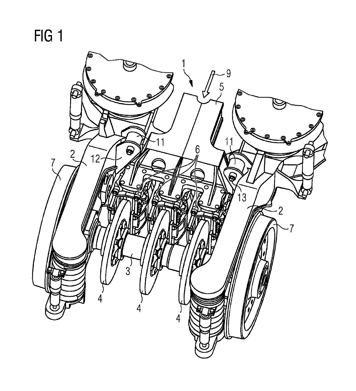
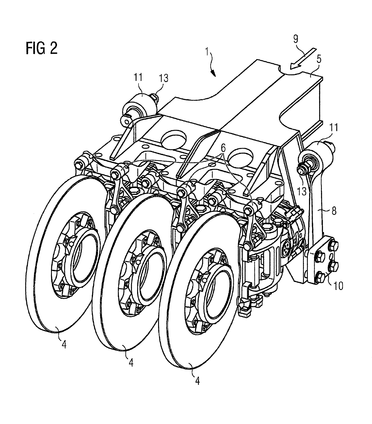
[0028]FIG. 1 shows a disk brake 1, which is arranged on the vehicle frame between the longitudinal supports 2 thereof. A disk brake 1 consists of one or in this case several brake disks 4 connected to the wheel axle 3, and of the brake carrier 5, to which the (in this case three) brake calipers 6, which are also called a caliper unit, are attached. A respective brake caliper 6 encompasses a respective brake disk 4, and on each side of the brake disk 4 contains brake pads and the brake pistons, which press the brake pads axially against the brake disk 4.

[0029]FIG. 1 illustrates only half the chassis, where the entire chassis comprises two wheel axles 3 parallel to one another, each with two wheels 7. The second half (not illustrated) of the chassis is designed to be symmetrical to the half illustrated. The brake carrier 5 thus likewise continues symmetrically and hence has six brake calipers 6 in total. The device in accordance with the invention can, however, also be formed precisel...


PUM


Abstract

A device for reducing vibrations of a vehicle, in particular a rail vehicle, wherein the device includes at least a vehicle frame, a brake carrier, a mechanically operative brake unit and a suspension bracket that interconnects the vehicle frame and brake carrier, where the suspension bracket includes at least one element elastically connecting the vehicle frame to the brake carrier that allows movement of the brake carrier in the transverse direction of the vehicle frame in order to dampen vibrations.

Description

CROSS-REFERENCE TO RELATED APPLICATIONS[0001]This is a U.S. national stage of application No. PCT / EP2014 / 074257 filed 11 Nov. 2014. Priority is claimed on Austrian Application No. A50757 / 2013 filed 13 Nov. 2013, the content of which is incorporated herein by reference in its entirety.BACKGROUND OF THE INVENTION1. Field of the Invention[0002]The invention relates to a device for reducing vibrations of a vehicle, in particular a rail vehicle, where the device comprises at least a vehicle frame, a brake carrier of a mechanically operative brake unit and a suspension bracket that interconnects the vehicle frame and brake carrier.[0003]In this case, particularly disk brakes and shoe brakes are regarded as mechanically operative brake units, but not magnetic rail brakes or eddy-current brakes.2. Description of the Related Art[0004]When rail vehicles move away on the track, vibrations in the chassis occur as a result of the wheel / rail contact, taking the form of air-borne or body-borne noi...

Claims


Application Information

Patent Timeline
Patent Type & Authority Patents(United States)
IPC IPC(8): B61H13/36F16D65/04B61F3/02F16D57/00B61F1/00F16D65/00F16D55/224B61H5/00F16D65/02F16F15/04F16F15/02F16D55/00
Inventor KÜTER, CHRISTIANRACKL, HUGOSCHOBEGGER, GERALDTEICHMANN, MARTIN
Owner SIEMENS MOBILITY AUSTRIA GMBH
Why Eureka
Try Eureka