Pivot posts and trimmer heads utilizing the same

a technology of rotating posts and trimmer heads, applied in the field of rotating posts, can solve the problems of affecting the use of trimmer heads, the wear of the trimmer line, and the need to replace, so as to improve the geometric shape, improve the effect of material selection, and facilitate the removal of used strips of folded monofilamen

Active Publication Date: 2019-09-03
SHAKESPEARE CO
View PDF16 Cites 1 Cited by
  • Summary
  • Abstract
  • Description
  • Claims
  • Application Information

AI Technical Summary

Benefits of technology

[0014]The proposed invention improves the design of pivot posts for holding strips of folded line in trimmer heads. The novel posts of the present invention are the type that can be held in a trimmer head by sandwiching a lower flange of the pivot post between a lower portion and an upper portion of the trimmer head.
[0015]The improved post designs are intended to pivot about the post's central vertical axis. A first embodiment of the improved post designs can be molded from 100% plastic and takes advantage of improved geometry to prevent the flared portion of trimmer line from becoming wedged in either of the two passageways. A second embodiment of the post design utilizes the combination of plastic and metal components in a new geometry to create a post that is mainly plastic with metal incorporated in the central vertical axis to minimize wear and fusion between the post and the line. A third embodiment of the post design eliminates the two parallel passageways known in the prior art. These two parallel passageways are replaced with a single channel or passageway. One or more metal pins are used external to the channel to retain the folded portion of the line. This novel post design has more room within its single channel which makes the design more forgiving of deformed segments of trimmer line that might get pulled into the channel. Additional post designs are within the scope of the present invention that include variations of the above concepts.
[0016]One of the objectives of the present invention is to provide a novel, improved design for pivoting line holding mechanisms where the pivoting posts are designed to hold a folded strip of line.

Problems solved by technology

Over time, the trimmer line becomes worn and must be replaced.
This is frustrating to the consumer.
Additionally, over time the portion of plastic separating the two straight through holes can become worn at the two opposite ends.
Over time, this sawing motion can create a recessed area where the line can be pulled further into the body of the pivot post, making removal of the line even more difficult.
The portion of plastic separating the two through holes continues to wear more and more over time and the post must eventually be replaced.
The above discussed sawing motion can also cause frictional melting of either the trimmer line surface or the surface of the portion of the plastic pivot post separating the two through passageways.
This can make removal of the used portion of the line very difficult, even when using needle nosed pliers to grip the line remnant.
Another complaint is that the two legs of the trimmer line break flush with a slanted surface of the pivot post, leaving the folded portion of line still in place in the post and the short legs of line still inside the two parallel through holes.
These short pieces can be difficult to remove.
It is thought that the trimmer line wraps around the trunk of the volunteer, thus interfering with the ability of the line to pivot out of the way.

Method used


Image

  • Pivot posts and trimmer heads utilizing the same
  • Pivot posts and trimmer heads utilizing the same
  • Pivot posts and trimmer heads utilizing the same

Examples


first embodiment

of the Present Invention

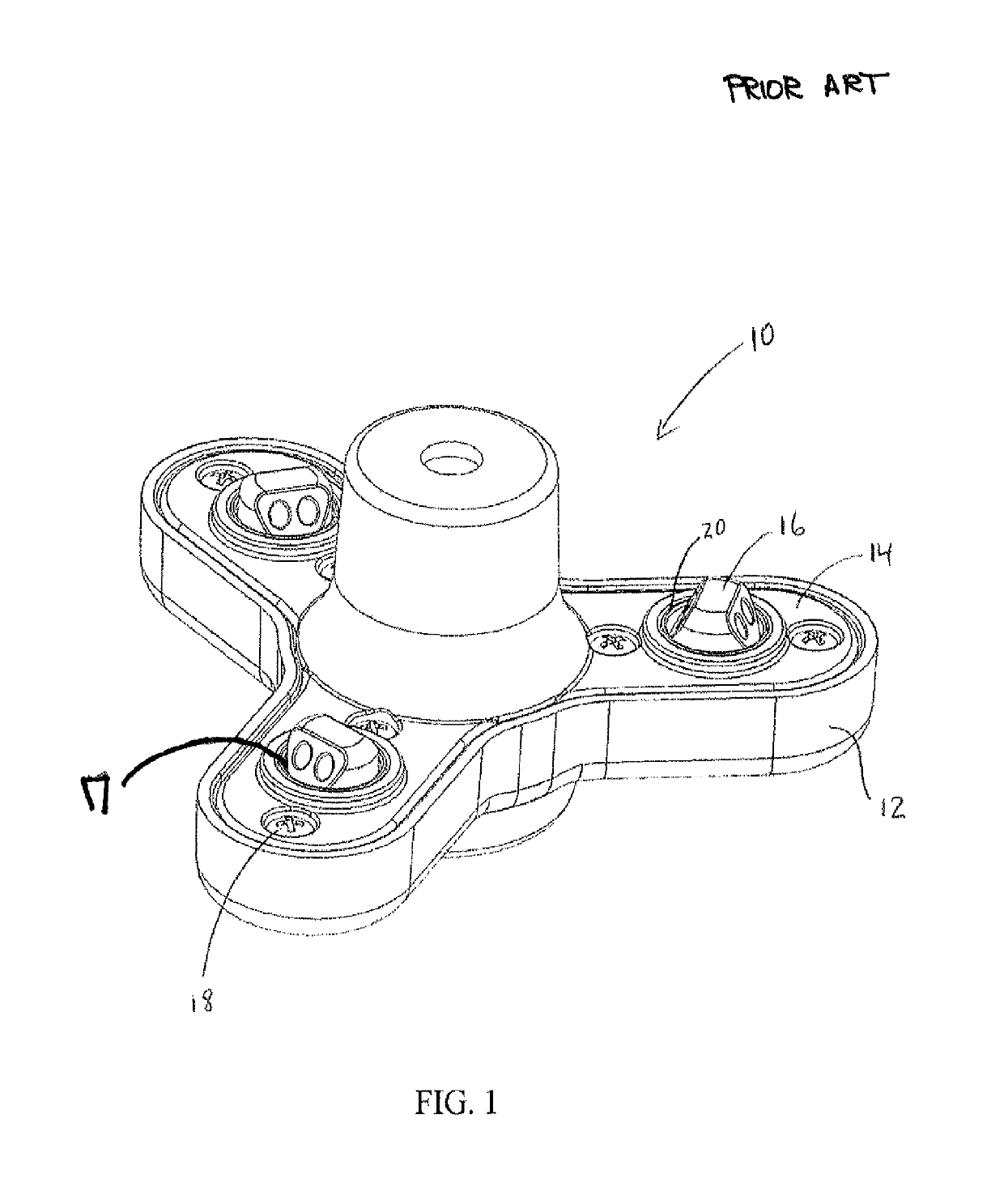
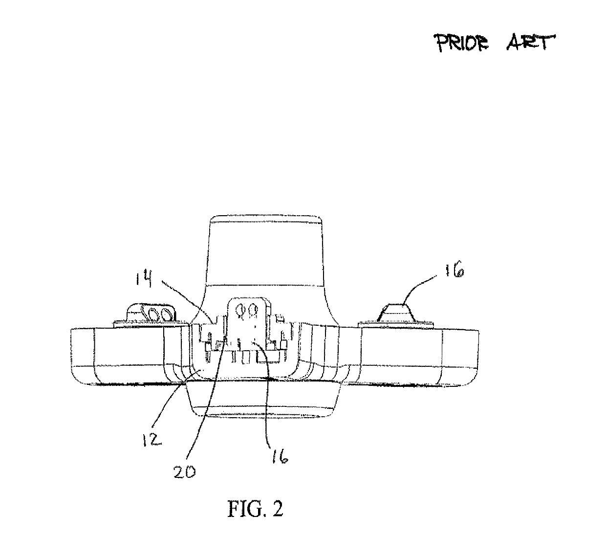
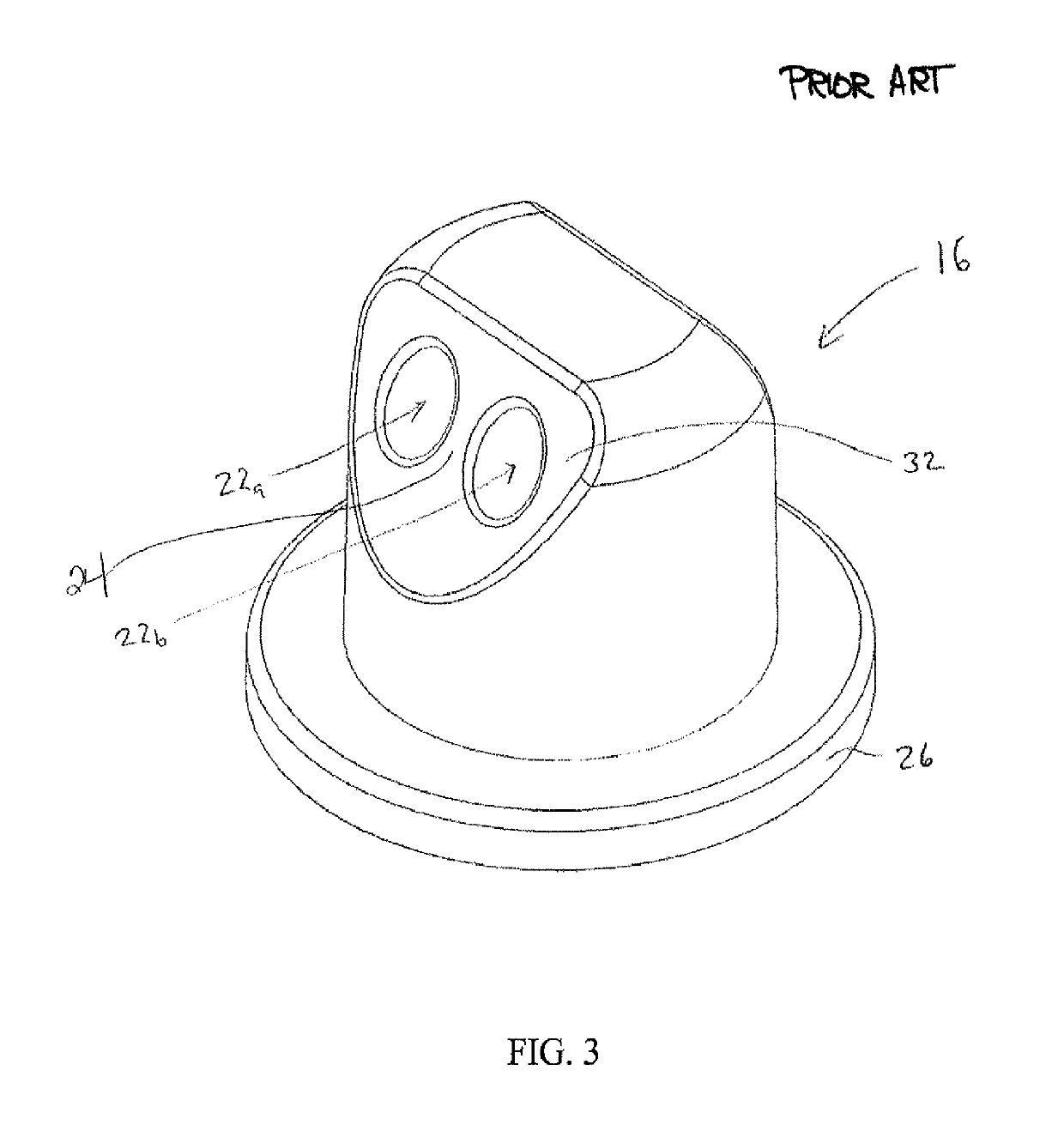
[0065]An improved pivot post design is shown in FIGS. 9-13. The improved pivot post 116 can replace the pivot posts 16 shown in FIG. 1 without modification of the remaining structure of the Ugly™ Head trimmer head model. The thickness and diameter of the lower flange 126 can be identical to that of lower flange 26 on the prior art pivot post 16. As such, improved pivot post 116 can be switched in for prior art pivot post 16 in virtually any model of trimmer head without changing the existing structure of the trimmer head. The overall heights of the pivot post 16 of the prior art and of the pivot post 116 of this invention can also easily be the same. The pivot post of the present invention 116 can be used in any of the existing commercial Shakespeare heads without modification of the heads.

[0066]The improved pivot post 116 comprises a generally cylindrical main housing portion 119 and a lower flange 126. The main housing portion 119 comprises two parallel str...

second embodiment

of the Present Invention

[0079]A second improved pivot post 216 is shown in FIGS. 14-21. The improved pivot post 216 comprises a housing 217 and a metal post 215. The housing is depicted in FIGS. 19 & 21. It comprises a generally cylindrical main housing portion 219 and a lower flange 226. Main housing portion 219 has a single central passageway 260 oriented perpendicular to the axis of rotation of pivot post 216 and extending the entire diameter through as shown in FIG. 19. As shown in the present drawings and embodiment, passageway 260 is horizontally oriented. Metal post 215 extends vertically downward through the center of passageway 260, effectively forming first side 260a of passageway and second side 260b of passageway. First and second sides 260a, 260b support and retain the two separate legs of a folded strip of trimmer line. FIG. 14 depicts the pivot post assembly 216 after metal post 215 is installed in the housing 217.

[0080]To facilitate installation of the metal post 215...

third embodiment

[0087]A third improved pivot post design 316 is shown in FIGS. 22-31. The improved pivot post 316 comprises housing 317 and first and second metal pins 315a and 315b. The housing is depicted in FIGS. 23, 24 & 29. It has a single central passageway 360 as shown in FIG. 23 extending through the entire diameter of housing. Housing 317 comprises a generally cylindrical main housing portion 319 and lower flange 326. Housing 317 is assembled with first and second metal pins 315a and 315b which are at least partially external to the passageway. Passageway 360 comprises first and second entrances 360a, 360b for receiving the trimmer line ends. FIG. 22 depicts the pivot post assembly 316 with first and second metal pins 315a and 315b installed in the housing 317, which supports and retains a folded strip of trimmer line 132.

[0088]To facilitate installation of the metal pins, the housing 317 has two receiving apertures 348a and 348b shown in FIG. 29. The receiving apertures are accessible fro...


PUM


Abstract

A trimmer head having at least two pivoting line holders for holding multiple folded strips of trimming line is presented wherein said pivoting line holders are retained within said housing between said housing and said cover and extend upward through apertures in said cover, said line holders being capable of movement around a vertical axis of rotation, at least three embodiments are disclosed which provide a rounded landing for supporting the inner radius of a folded strip of trimming line, the rounded geometry of the landing prevents line stress and breakage, the various embodiments include a pivot post having two parallel straight through holes with a rounded vertical wall between the through holes, a single open passageway having a center metal post, and a single open passageway having a series of at least two metal pins through the center of the passageway.

Description

CROSS-REFERENCE TO RELATED APPLICATIONS[0001]This application is a U.S. National Phase Application of International Application PCT Application No. PCT / US2015 / 021694 filed on Mar. 20, 2015, which claims the benefit of priority from U.S. Provisional Patent Application No. 61 / 955,949, filed Mar. 20, 2014; U.S. Provisional Patent Application No. 61 / 989,561, filed May 7, 2014; and U.S. Provisional Patent Application No. 62 / 000,177, filed May 19, 2014, all of which are incorporated by reference as if fully rewritten herein.FIELD OF THE INVENTION[0002]The present invention relates to trimmer heads for rotary trimmers using monofilament as a means for cutting vegetation; and, more specifically it relates to trimmer heads with an improved means to hold folded strips of trimmer line, the means being capable of pivoting to minimize line breakage upon impact with solid objects and dense vegetation.BACKGROUND OF THE INVENTION[0003]There are many names commonly used interchangeably for the monof...

Claims


Application Information

Patent Timeline
Patent Type & Authority Patents(United States)
IPC IPC(8): A01D34/416
CPCA01D34/4166
Inventor SKINNER, DAVID B.SEARFOSS, BRIANLIU, WENWANG, LINYANG, JACK
Owner SHAKESPEARE CO
Why Eureka
Try Eureka