
Incombustible decorative sheet, metal decorative member and method for fabricating a metal decorative member

a metal decorative and incombustible technology, applied in the direction of building components, layered product treatment, synthetic resin layered products, etc., can solve the problems of low processability and incombustibility, low oil resistance and solvent resistance, and low contamination resistance, so as to achieve good incombustibility, processability and incombustibility of decorative sheets

Active Publication Date: 2019-09-03
TOPPAN PRINTING CO LTD
View PDF42 Cites 0 Cited by
  • Summary
  • Abstract
  • Description
  • Claims
  • Application Information

AI Technical Summary

Benefits of technology

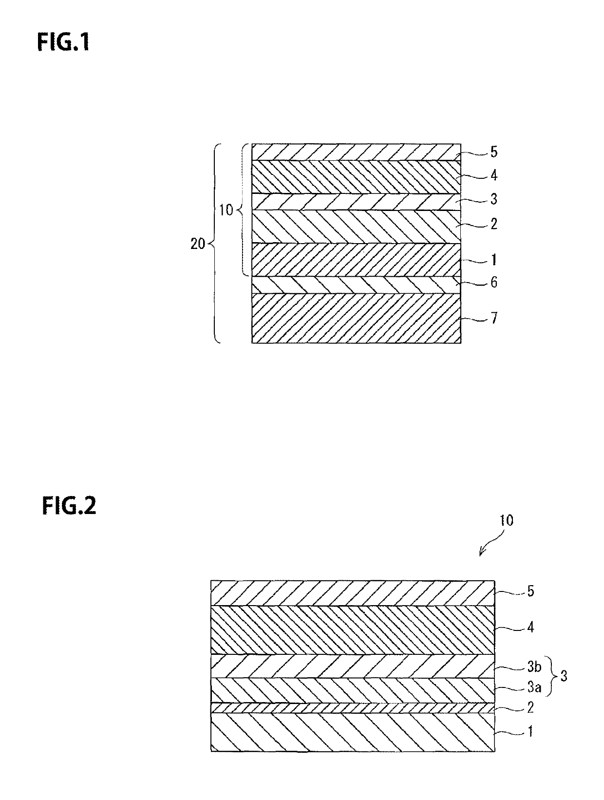
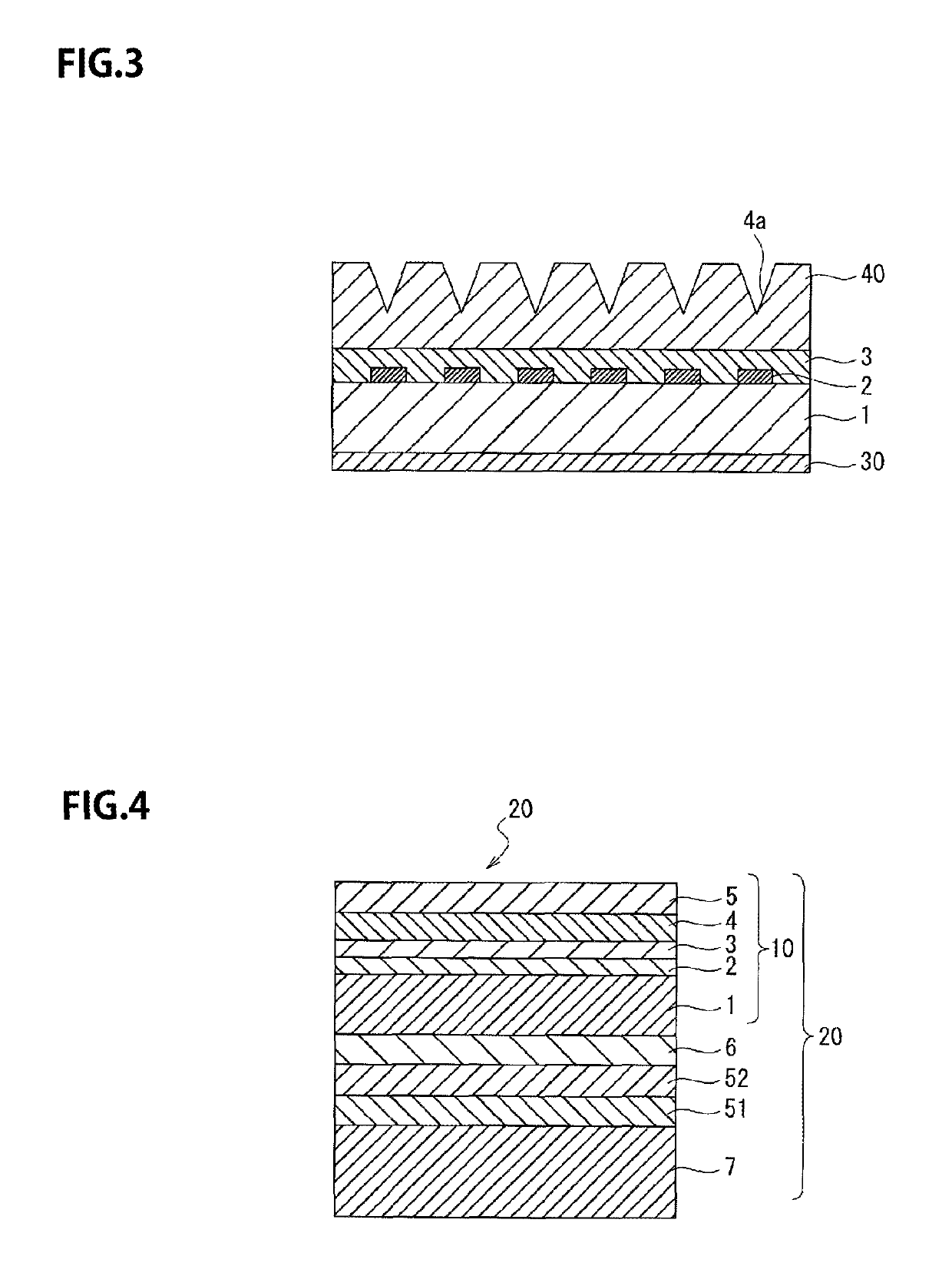
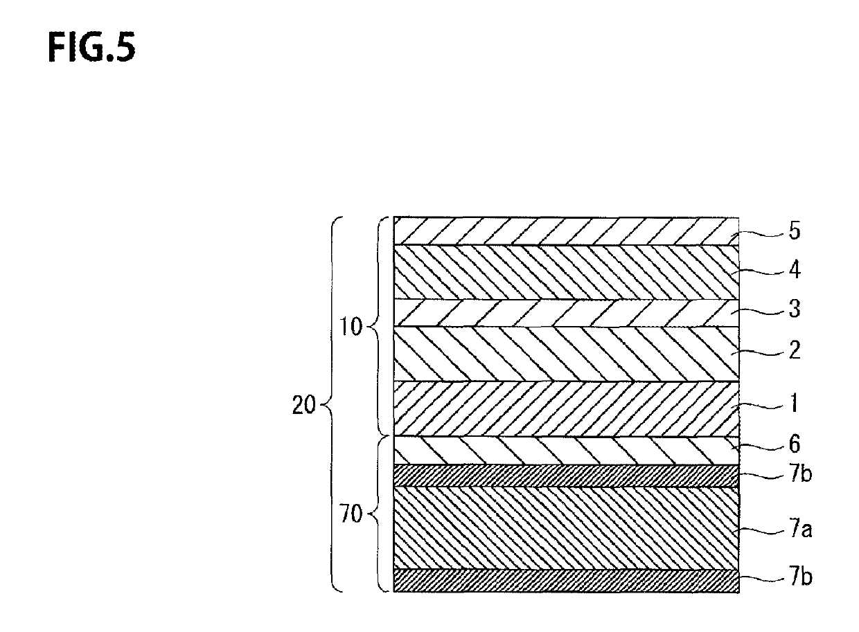
[0010]According to one embodiment, a weather-resistant resin layer and a fluorine resin layer are formed on a substrate layer in this order, thus ensuring weatherability, contamination resistance and solvent resistance.
[0011]The ratio by mass between the acrylic resin-based rubber and the acrylic resin both serving as the weather-resistant resin layer is set within a range of 30:70 to 60:40, and the ratio between the thickness of the fluorine resin layer and the thickness of the weather-resistant resin layer is set within a range of 10:90 to 40:60, the incombustibility, processability and weatherability of the decorative sheet can be all made good.
[0012]Hence, according to one embodiment of the invention, there can be provided a decorative sheet and a metal decorative member, which are able to make good all of incombustibility, processability and weatherability while ensuring weatherability, contamination resistance and solvent resistance.

Problems solved by technology

However, although the acrylic resin is excellent in weatherability, contamination resistance, oil resistance and solvent resistance are low.
Accordingly, the above conventional decorative sheet is apt to be attached with dirt, coupled with the problem that the attached dirt cannot be wiped off with a solvent.
The above conventional decorative sheet also has a problem in that processability and incombustibility are low.

Method used


Image

  • Incombustible decorative sheet, metal decorative member and method for fabricating a metal decorative member
  • Incombustible decorative sheet, metal decorative member and method for fabricating a metal decorative member
  • Incombustible decorative sheet, metal decorative member and method for fabricating a metal decorative member

Examples


examples

[0212]Next, examples based on the present invention are illustrated.

first example

Example 1

[0213]In Example 1, a substrate layer 1 was provided using a colored polypropylene resin. The thickness of the substrate layer 1 was set at 70 μm. The substrate layer 1 was subjected to corona discharge treatment on front and back surfaces thereof, respectively. Subsequently, a grain pattern was printed by gravure printing using a urethane printing ink to provide a design pattern layer 2 on the surface of the substrate layer 1. Thereafter, a back surface primer layer was formed on the back surface of the substrate layer 1 by gravure printing using a coating solution for back surface primer layer. The formulation of the coating solution for back surface primer layer was one which was comprised of 100 parts by mass of a two-part curing polyester urethane (wherein a polyester polyol and a polyisocyanate was mixed at a ratio (mass ratio) of 100:5) and 20 parts by mass of a diluent solvent (which was a mixed solvent of ethyl acetate and methyl isobutyl ketone at a ratio (mass ra...

second example

Example 1

[0244]In Example 1, a substrate layer 1 was provided using a colored polypropylene resin as a polyolefin resin. The substrate layer 1 had a thickness of 70 μm. The substrate layer 1 was subjected to corona discharge treatment on front and back surfaces thereof, respectively. A grain pattern was subsequently printed by gravure printing using a urethane printing ink to provide a design pattern layer 2 on the surface of the substrate layer 1. Thereafter, a back surface primer layer was formed on the back surface of the substrate layer 1 by gravure printing using a coating solution for back surface primer layer. The formulation of the coating solution for back surface primer layer was one which was comprised of 100 parts by mass of a two-part curing polyester urethane (wherein a polyester polyol and a polyisocyanate was mixed at a ratio (mass ratio) of 100:5) and 20 parts by mass of a diluent solvent (which was a mixed solvent of ethyl acetate and methyl isobutyl ketone at a ra...


PUM


Abstract

A decorative sheet which ensures good incombustibility, processability and weatherability along with weatherability, contamination resistance and solvent resistance. An incombustible decorative sheet having incombustibility includes a weather-resistant resin layer and a fluorine resin layer laminated on a substrate layer in this order, wherein the weather-resistant resin layer is made of a mixture of an acrylic resin and an acrylic resin-based rubber having a ratio by mass between the acrylic resin-based rubber and the acrylic resin within a range of 30:70 to 60:40. The ratio between the fluorine resin layer and the weather-resistant resin layer is within a range of 10:90 to 40:60.

Description

CROSS-REFERENCE TO RELATED PATENT APPLICATIONS[0001]This application is a continuation application filed under 35 U.S.C. § 111(a) claiming the benefit under 35 U.S.C. §§ 120 and 365(c) of International Application No. PCT / JP2015 / 002581, filed on May 22, 2015, which is based upon and claims the benefit of priority of Japanese Patent Application No. 2015-013273, filed on Jan. 27, 2015; Japanese Patent Application No. 2015-013287, filed on Jan. 27, 2015; Japanese Patent Application No. 2015-017200, filed on Jan. 30, 2015; Japanese Patent Application No. 2015-017201, filed on Jan. 30, 2015; Japanese Patent Application No. 2015-024087, filed on Feb. 10, 2015; Japanese Patent Application No. 2015-024088, filed on Feb. 10, 2015; Japanese Patent Application No. 2015-024089, filed on Feb. 10, 2015; Japanese Patent Application No. 2015-024090, filed on Feb. 10, 2015; Japanese Patent Application No. 2015-024366, filed on Feb. 10, 2015; Japanese Patent Application No. 2015-035146, filed on Feb....

Claims


Application Information

Patent Timeline
Patent Type & Authority Patents(United States)
IPC IPC(8): B32B7/02B32B15/088B32B15/085B32B15/082B32B27/00E04F13/07E04B1/94B32B37/06B32B27/36B32B27/30B32B15/20B32B7/12B32B15/08B32B15/09B32B38/18B32B3/30B32B27/34B32B27/32B32B27/20B32B27/18B32B27/16B32B27/08B32B15/18E04F13/00
CPCB32B15/082B32B15/18B32B27/08B32B27/304B32B15/08B32B15/085B32B15/088B32B15/09B32B27/16B32B27/18B32B27/302B32B27/308B32B27/32B32B27/322B32B27/34B32B27/36B32B27/365B32B37/06E04B1/942B32B27/00E04F13/07B32B15/20B32B27/20B32B27/30B32B27/306B32B38/1866B32B7/12B32B3/30B32B2307/408B32B2255/06B32B2264/0207B32B2255/26B32B2264/102B32B2307/412B32B2307/712B32B2307/718B32B2307/732B32B2309/105E04F13/002B32B2451/00B32B2307/3065B32B2307/406B32B2255/10B32B2270/00C09J175/06
Inventor SHINMYO, KATSUYUKITOMINAGA, TAKASHI
Owner TOPPAN PRINTING CO LTD
Learn More