Method for introducing a borehole into the soil and soil drilling device and use thereof

a drilling device and soil technology, applied in the direction of borehole/well accessories, directional drilling, survey, etc., can solve the problems of time-consuming and expensive convergence boring, inability to insert pipes into the resulting borehole, and limited “accuracy” of achieving convergence boring, etc., to achieve easy detection, low cost, and soil loose

Active Publication Date: 2019-09-03
TRACTO TECHN
View PDF15 Cites 0 Cited by
  • Summary
  • Abstract
  • Description
  • Claims
  • Application Information

AI Technical Summary

Benefits of technology

[0009]The drill head can in particular be a drill head in which nozzles are provided, through which drilling fluid can be discharged into the soil in the region around the drill head. In particular, a drilling fluid which contains bentonite, preferably in the form of particles, can be used. The drilling fluid can be pressurized, so that the pressurized drilling fluid can discharge from the nozzles on the drill head. Thanks to the drilling fluid, a loosening of the soil in the region around the drill head can occur. The drilling fluid discharging from the drill head, which can be pressurized, can loosen the soil. The soil drilling device can have a suitable pump for pressurizing the drilling fluid. In order to supply the drilling fluid to the drill head, the drill pipe, which connects the soil drilling device to the drill head, can have a conduit by means of which the drilling fluid is transported to the drill head for example from a storage container, which can in particular be arranged at the surface.
[0010]In one preferred embodiment, the detection unit is designed such that it permits emission and reception of electromagnetic radiation. The detection unit can be part of a unit for emission and reception of electromagnetic radiation. The detection unit can also be separate from a unit for emission and reception of electromagnetic radiation. According to the invention, “electromagnetic radiation” comprises any electromagnetic wave, in particular radar waves, so that the detection unit can be formed as a radar. A radar makes it easy to detect the outer contour of other objects in the soil. In particular, a radar antenna allows the detection of the form and location of another drill head because the other drill head is easily detectable due to the intense reflection of the metal thereof. In particular, the distance from the other of the two drill heads can be easily determined.
[0011]In one preferred embodiment, in particular the front contour of the other drill head can be determined. For this purpose, at least one of the following parameters of the other drill head describing the location of the front contour can be detected: pitch, roll (tool face position), axis (level-alignment and side-alignment). The detection of at least one of the above parameters allows precise convergence boring by permitting axis- and location-precise convergence.
[0012]In one preferred embodiment, one of the two drill heads can, after slow retraction of the other, enter precisely and without deviation into the borehole of the retracting drill head and in particular pass through same. This permits a joint borehole widening and a joint pipe or cable insertion. This can for example make long boreholes possible, which can be bored with relatively small soil drilling devices and therefore inexpensively.
[0018]In one preferred embodiment, the detection unit has a unit for pattern recognition, by means of which the other drill head which is to be recognized can be easily identified.

Problems solved by technology

The to-date attainable “accuracy” in convergence boring is limited and associated with high costs.
A to-date attainable “accuracy” of + / −0.5 meters appears to be sufficient at first glance, however, if the two boreholes do not join together in a precise manner, it is not possible for example to insert a pipe into the resulting borehole.
Convergence boring is thus time-consuming and expensive.
The artificial magnetic fields or artificial magnetic target points must be introduced at predetermined locations, which also involves significant effort.
Such a system is expensive and there is still a risk with respect to the axis- and level-identical alignment of the two drill heads relative to one another specifically in the region of the target section, so that this system too is associated with outlay in the form of time and corrective measures, which is also expensive.

Method used


Image

  • Method for introducing a borehole into the soil and soil drilling device and use thereof

Examples


Embodiment Construction

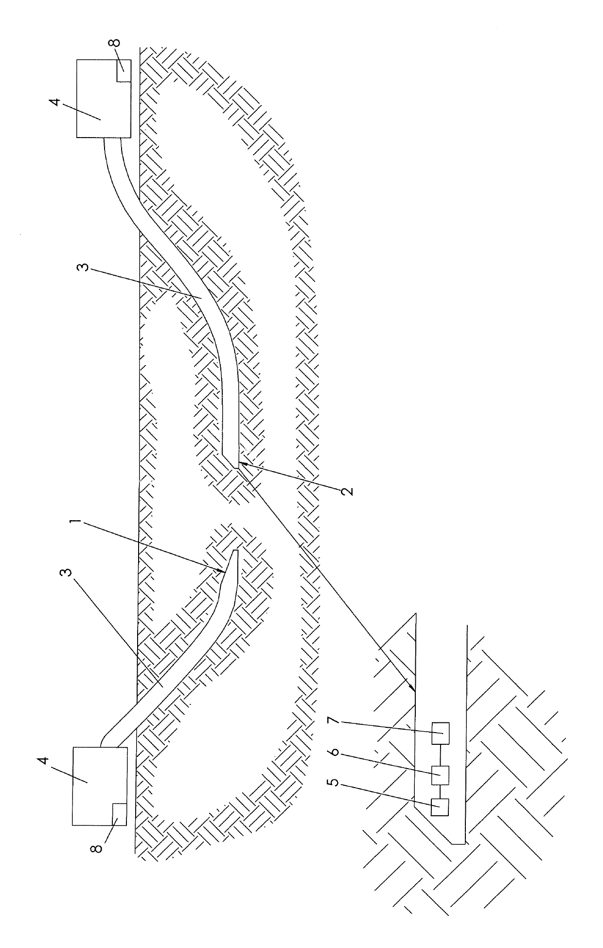
[0023]FIG. 1 shows an introduction of a borehole into the soil by means of two drill heads 1, 2. The drill heads 1, 2 are connected to a drill pipe 3 or drill string, which consists of a plurality of drill pipe lengths connected to one another. The drill pipe lengths are connected to one another along the course of the bore. The drill heads 1, 2 are advanced and (temporarily) rotatively driven by means of the drill pipe 3 of a driving device 4 arranged on the earth's surface. The rotary driving on the one hand serves to improve the advancement of the drill heads 1, 2 in the soil and on the other hand a control function is thereby achieved in conjunction with the formation of at least one of the two drill heads 1, 2 as a slanted drill head. When the drill head 1, 2 designed as a slanted drill head is advanced through the soil, the slanted surface of the drill head 1, 2 creates a deflection, the effect of which is offset across a full rotation of the drill head 1, 2. If the drill head...


PUM


Abstract

A method for introducing a borehole into the ground includes advancing at least two drill heads, detecting one of the two drill heads is detected by a detection unit on the other drill head, and adapting the direction of advance of at least one of the drill heads relative to the other drill head.

Description

CROSS-REFERENCE TO RELATED APPLICATIONS[0001]This application claims priority pursuant to 35 U.S.C. 119(a)-(d) to German Application No. 10 2016 002 479.8 filed Mar. 3, 2016, the entire contents of which is incorporated herein by reference for all purposes.FIELD OF THE INVENTION[0002]The invention relates to a method for introducing a borehole into the soil with two converging drill heads and a soil drilling device with a drill head.BACKGROUND OF THE INVENTION[0003]Convergence boring is known, wherein two soil drilling devices each construct a borehole, with the alignment relative to one another being such that a continuous borehole should be produced, which the two boreholes thus meet at at their respective target section (endpoint). The to-date attainable “accuracy” in convergence boring is limited and associated with high costs. A to-date attainable “accuracy” of + / −0.5 meters appears to be sufficient at first glance, however, if the two boreholes do not join together in a precis...

Claims


Application Information

Patent Timeline
Patent Type & Authority Patents(United States)
IPC IPC(8): E21B47/024E21B47/09E21B47/022E21B7/04
CPCE21B47/02216E21B47/024E21B47/0905E21B7/046E21B47/0228E21B47/092
Inventor BAYER, HANS-JOACHIM
Owner TRACTO TECHN
Why Eureka
Try Eureka