

Marking sparse areas on maps
Active Publication Date: 2019-09-03
BIOSENSE WEBSTER (ISRAEL) LTD
View PDF24 Cites 1 Cited by
- Summary
- Abstract
- Description
- Claims
- Application Information
AI Technical Summary
Benefits of technology
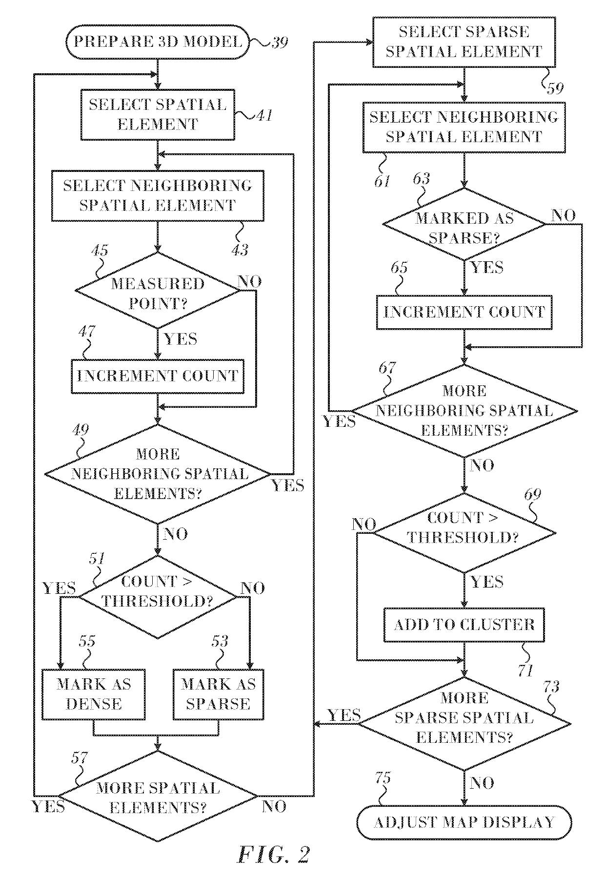
The invention is a method and apparatus for creating a 3-dimensional model of a heart and utilizing information from measured points on the surface of the heart. This model is created by interpolating values between measured points and analyzing the density of the measured points within a certain distance of each explained in more detail below. The model can also be modified based on the density of the measured points, such as adding shading or other features to the map. The technical effect of this invention is to provide a useful tool for analyzing the structure and function of the heart in a more accurate and precise way.
Problems solved by technology
One way for the physician to estimate the quality of the interpolation is to display the measured points, but this is unsatisfactory because of visual overload from other information incorporated into the map (e.g., catheter icons).
Method used
View moreImage
Smart ImageViewing Examples

Examples
example
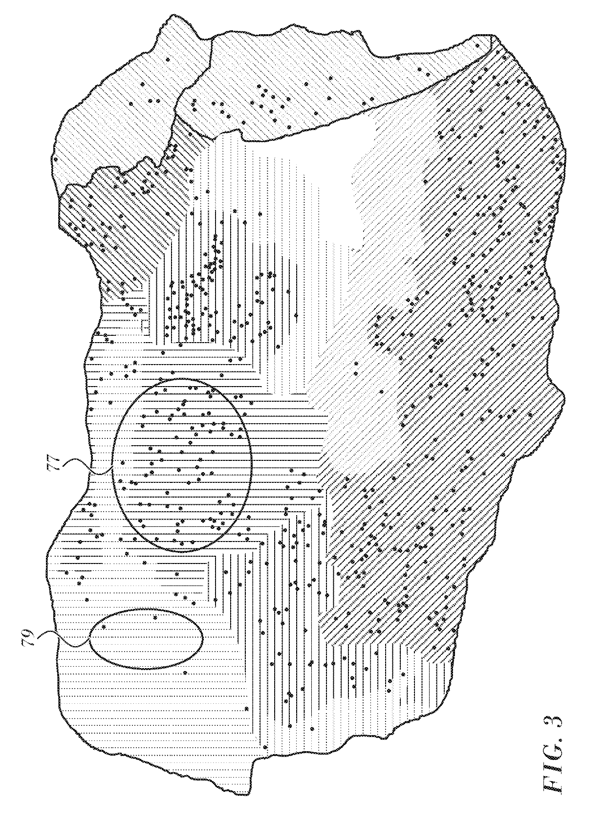
[0062]Reference is now made to FIG. 3, which is an LAT map of the heart, which is prepared in accordance with an embodiment of the invention. Measured points are indicated by dots. However, as mentioned above, the display of the measured points on such maps is optional. In region 77 measured points are relatively plentiful in an area indicated by bold hatching, while in region 79 there are fewer measured points. This is indicated by de-emphasizing the intensity of the hatching lines in the region 79. The same effects in hatching are seen in several other areas of the map according to whether the dots in those areas are plentiful or sparse.
Login to View More PUM
 Abstract
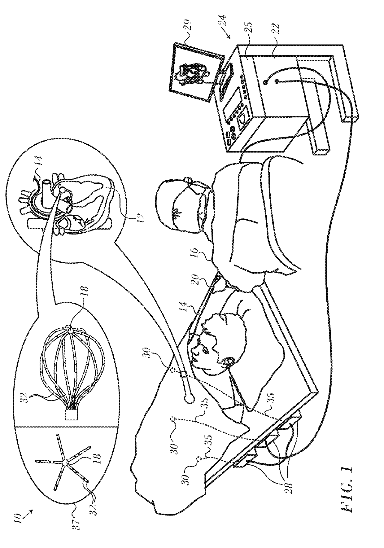
Values of a physiologic parameter at respective measured points in a heart are obtained. A 3-dimensional model of the heart is constructed, which includes first spatial elements that include the measured points and second spatial elements that do not include the measured points. The values of the parameter in the second spatial elements are interpolated and regional densities of the measured points in the model determined. The values of the parameter at the first spatial elements and the second spatial elements are displayed on a functional map of the heart, and a graphical characteristic of the map is modified responsively to the regional densities.
Description
COPYRIGHT NOTICE[0001]A portion of the disclosure of this patent document contains material that is subject to copyright protection. The copyright owner has no objection to the facsimile reproduction by anyone of the patent document or the patent disclosure, as it appears in the Patent and Trademark Office patent file or records, but otherwise reserves all copyright rights whatsoever.BACKGROUND OF THE INVENTION1. Field of the Invention[0002]This invention relates to image data processing. More particularly, this invention relates to geometrically modeling objects for diagnosis by means of electric currents or magnetic fields.2. Description of the Related Art[0003]3-dimensional functional images of internal organs are useful in many catheter-based diagnostic and therapeutic applications, and real-time imaging is widely used during surgical procedures. For example, a map of a chamber of the heart may be a 3-dimensional map of the chamber surface, upon which is overlaid a color represe...
Claims
Login to View More Application Information
Patent Timeline
 Patent Type & AuthorityPatents(United States)
IPC IPC(8): G06T15/08G06T7/00G06T19/20A61B5/042G06T19/00G06T17/20G06T15/80A61B18/14A61B5/044A61B5/06A61B5/00A61B18/00
CPCG06T17/20G06T19/20G06T15/08A61B18/1492A61B5/0422G06T15/80G06T19/00G06T7/0014A61B5/044A61B2018/00351A61B2018/00357A61B2018/00577A61B2018/00791A61B2018/00839A61B2018/00875A61B2018/144A61B2018/00267A61B5/06G06T2207/30048G06T2210/41A61B5/6858A61B5/6859G06T15/10A61B5/318A61B5/283A61B5/287A61B5/339
InventorKATZ, NATAN SHARONZAR, LIORCOHEN, BENJAMIN
OwnerBIOSENSE WEBSTER (ISRAEL) LTD