
Drum head

a drum head and drum technology, applied in the field of drum head, can solve the problem of not being able to obtain the native sound produced by the drum head,

Active Publication Date: 2019-09-03
YAMAHA CORP
View PDF14 Cites 0 Cited by
  • Summary
  • Abstract
  • Description
  • Claims
  • Application Information

AI Technical Summary

Benefits of technology

The present invention is for a drum head with a sensor that detects the vibration of the drum head without interfering with the vibration. This sensor is placed between the first and second films of the drum head, and it enables the detection of native sound produced by the drum without being affected by the sensor. This results in a more accurate and unobstructed sound output from the drum. In contrast, previous patents describe drum heads that have a pickup microphone pressed against the drum head, which may change the state of vibration and affect the sound produced by the drum. The present configuration ensures that the sensor does not interfere with the vibration of the drum head, resulting in a more accurate and unobstructed sound output.

Problems solved by technology

Thus, even if the pulse signal output from the drum head disclosed in Patent Document 1 is converted to sound, it is impossible to obtain native sound to be produced by the drum.

Method used


Image

  • Drum head
  • Drum head
  • Drum head

Examples


embodiments

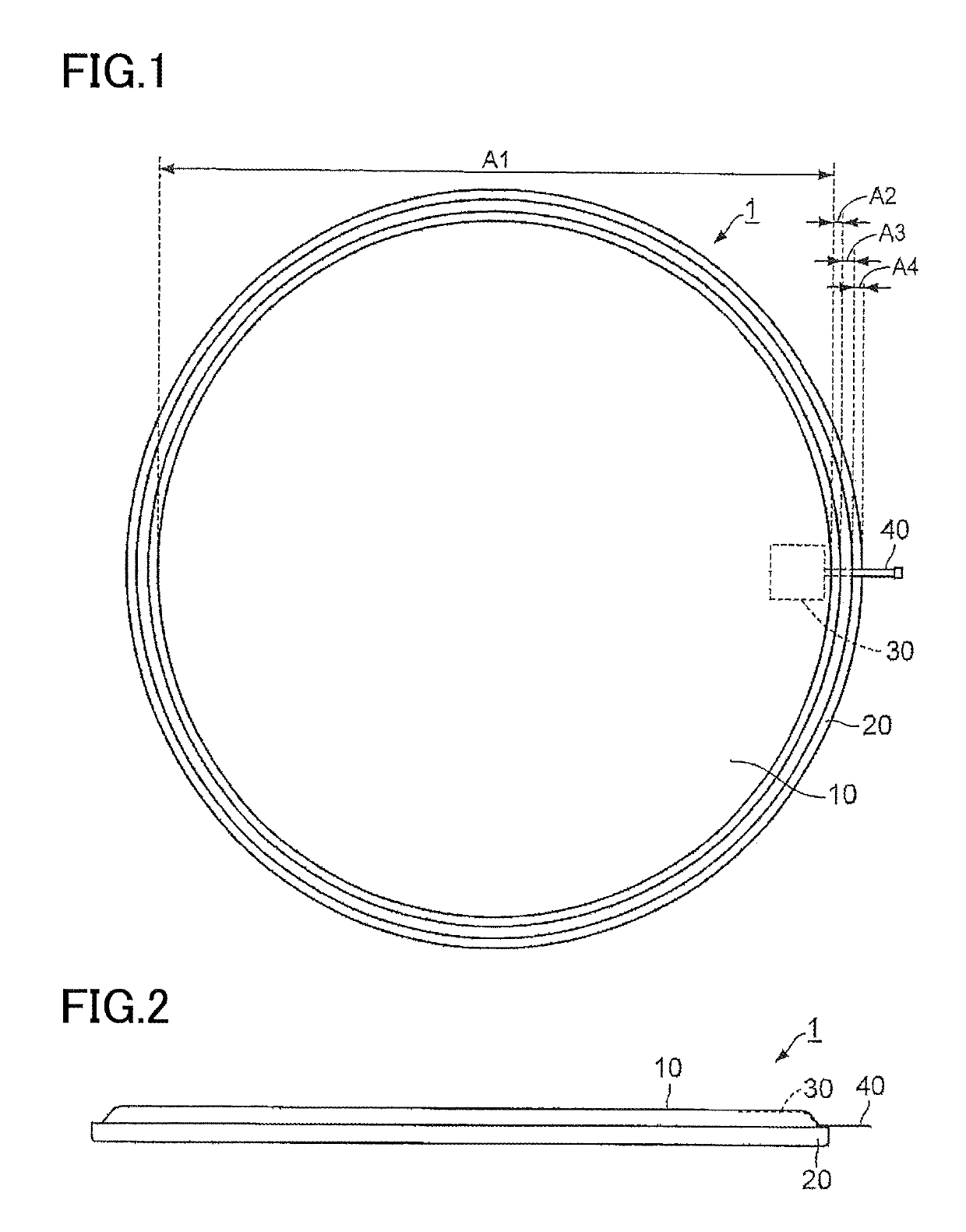
[0018]FIG. 1 is a plan view illustrating a configuration of a drum head 1 according to a first embodiment of the present invention. FIG. 2 is a side view illustrating the configuration of the drum head 1. The drum head 1 is stretched over an open end of a shell of a drum such as a tom, a snare drum, and a bass drum, for example.

[0019]The drum head 1 includes a head portion 10, a flesh hoop 20, a sensor 30, and a sensor tail40. The flesh hoop 20 is shaped like a ring having an inside diameter greater than an outside diameter of the shell. The head portion 10 is disposed inside the ring of the flesh hoop 20. The head portion 10 is shaped like a round film. An outer edge of the head portion 10 is connected to the flesh hoop 20, and the head portion 10 is held by the flesh hoop 20. The sensor 30 is provided near the outer edge of the head portion 10. The sensor tail 40 is connected to the sensor 30. The sensor tail 40 is a lead line for outputting a signal output from the sensor 30, to ...

second embodiment

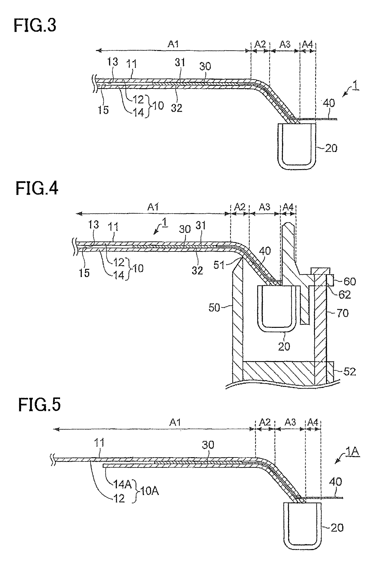
[0043]FIG. 5 is a cross-sectional view illustrating a configuration of a drum head 1A according to a second embodiment of the present invention. The drum head 1A according to the present embodiment is different from the drum head 1 according to the first embodiment in that the drum head 1A has a head portion 10A instead of the head portion 10. The head portion 10A is different from the head portion 10 in that the head portion 10A has a second film 14A instead of the second film 14.

[0044]In the present embodiment, the second film 14A is a ring-shaped film called what is called a ring mute. Since the second film 14A is shaped like a ring, the center of the head portion 10A does not have a two-layer structure. An outer edge portion of the head portion 10A however has a structure similar to that of the head portion 10. More specifically, a portion of the head portion 10A which is located near the outer edge in the flat region A1 as the bottom of the bowl has a two-layer structure which ...


PUM


Abstract

A drum head includes: a first film including a striking surface; a second film disposed opposed to a back surface of the first film which is back from the striking surface; and a sensor disposed between the first film and the second film and configured to output a signal related to vibration. The sensor includes: a first contact surface configured to contact the back surface of the first film without being secured to the back surface; and a second contact surface configured to contact a front surface of the second film without being secured to the front surface. A sensor tail of the sensor is secured to at least one of the first film and the second film located outside the shell when the first film and the second film are stretched over an open end of a shell.

Description

TECHNICAL FIELD[0001]The present invention relates to a drum head.BACKGROUND ART[0002]Patent Document 1 discloses a drum including a multilayer drum head including a first layer and a second layer. In the drum head disclosed in Patent Document 1, a force sensing register is disposed between the first layer and the second layer. The force sensing register is disposed on the entire drum head (more specifically, the entire strikable playing zone). A bias voltage is applied to the force sensing register. When the first layer is struck, a resistance value of a portion of the force sensing register which is located under a struck portion of the first layer changes at the instance of the strike. The drum head disclosed in Patent Document 1 outputs a pulse signal related to the change in the resistance value of the force sensing register. Thus, the force sensing register of the drum head disclosed in Patent Document 1 detects the timing of the strike.PRIOR ART DOCUMENTSPatent Documents[0003...

Claims


Application Information

Patent Timeline
Patent Type & Authority Patents(United States)
IPC IPC(8): G10D13/02G10H3/14
CPCG10H3/14G10H3/146G10D13/024G10D13/027G10H2220/535G10H2230/275G01H11/08G10D13/26G10D13/02G10D13/20
Inventor HASHIMOTO, RYUJI
Owner YAMAHA CORP
Learn More