
Automatically centering load support for shuttle vehicles having a variable receiving width

a technology of automatic centering and load support, which is applied in the direction of transportation and packaging, storage devices, etc., can solve the problems of complex design and manufacturing technology the connection established by flexible bands, load damage, and difficulty in adjusting the arrangement of overlapping plates between chassis parts, so as to reduce the size of the storage region, uniform space intervals, and sufficient stability

Active Publication Date: 2019-09-17
DEMATIC
View PDF45 Cites 6 Cited by
  • Summary
  • Abstract
  • Description
  • Claims
  • Application Information

AI Technical Summary

Benefits of technology

[0010]This has the advantage that a complex arrangement of a plurality of overlapping plates and the connection thereof via movable bands to provide a storage region are omitted. The storage region is formed merely by e.g. three supporting plates which can be arranged on two lateral holding rails of a connection structure. Therefore, a storage region is provided, of which the storage elements, i.e. supporting plates, are arranged more variably than when a closed storage region is provided by means of overlapping storage elements since a smaller minimum receiving width can be achieved because the plates do not have to be pushed one inside the other. Furthermore, variability of the minimum receiving width to be achieved can be easily achieved by a combination of different carrying plate widths.
[0021]In a further embodiment in accordance with the present invention, provision is made that the first lateral supporting plate is allocated to the first arm and the second lateral supporting plate is allocated to the second arm. This means that when the spaced interval between the two arms is changed, the two lateral supporting plates also move and therefore a load unit is supported on its sides irrespective of its size and of the size of the storage surface, i.e. storage stability is maximised.

Problems solved by technology

The arrangement of overlapping plates between the chassis portions and the connection established by flexible bands are complex in terms of design and manufacturing technology.
This design of the displaceable storage surface has the disadvantage that the storage surface is defined only by two supporting plates which are each arranged, at the sides of the storage surface, on the two chassis portions of the vehicle.
This can cause the load unit or the article to sag and thus render the transfer of articles from the shuttle to the intended storage shelf (and the other way round) more difficult or can even cause the load to become damaged if the goods to be loaded are unstable.
Also, in the case of an inaccuracy in the spaced interval between the two chassis portions and thus the supporting plates or in the case of the load unit having an irregular shape, a lack of support in the centre of the article-receiving region can even cause the load unit or article to slide through.
Corresponding problems can also occur during transport.

Method used


Image

  • Automatically centering load support for shuttle vehicles having a variable receiving width
  • Automatically centering load support for shuttle vehicles having a variable receiving width
  • Automatically centering load support for shuttle vehicles having a variable receiving width

Examples


Embodiment Construction

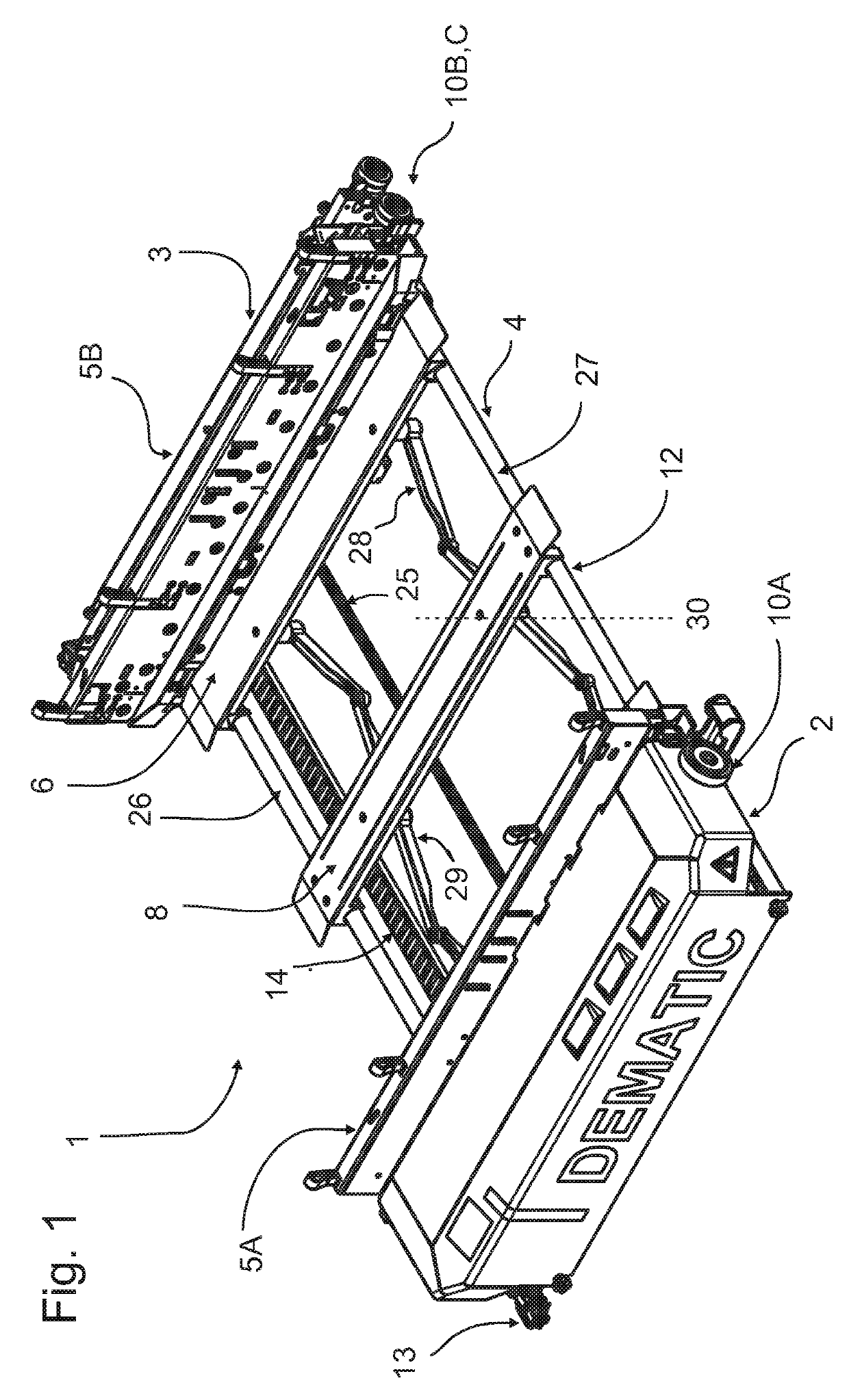
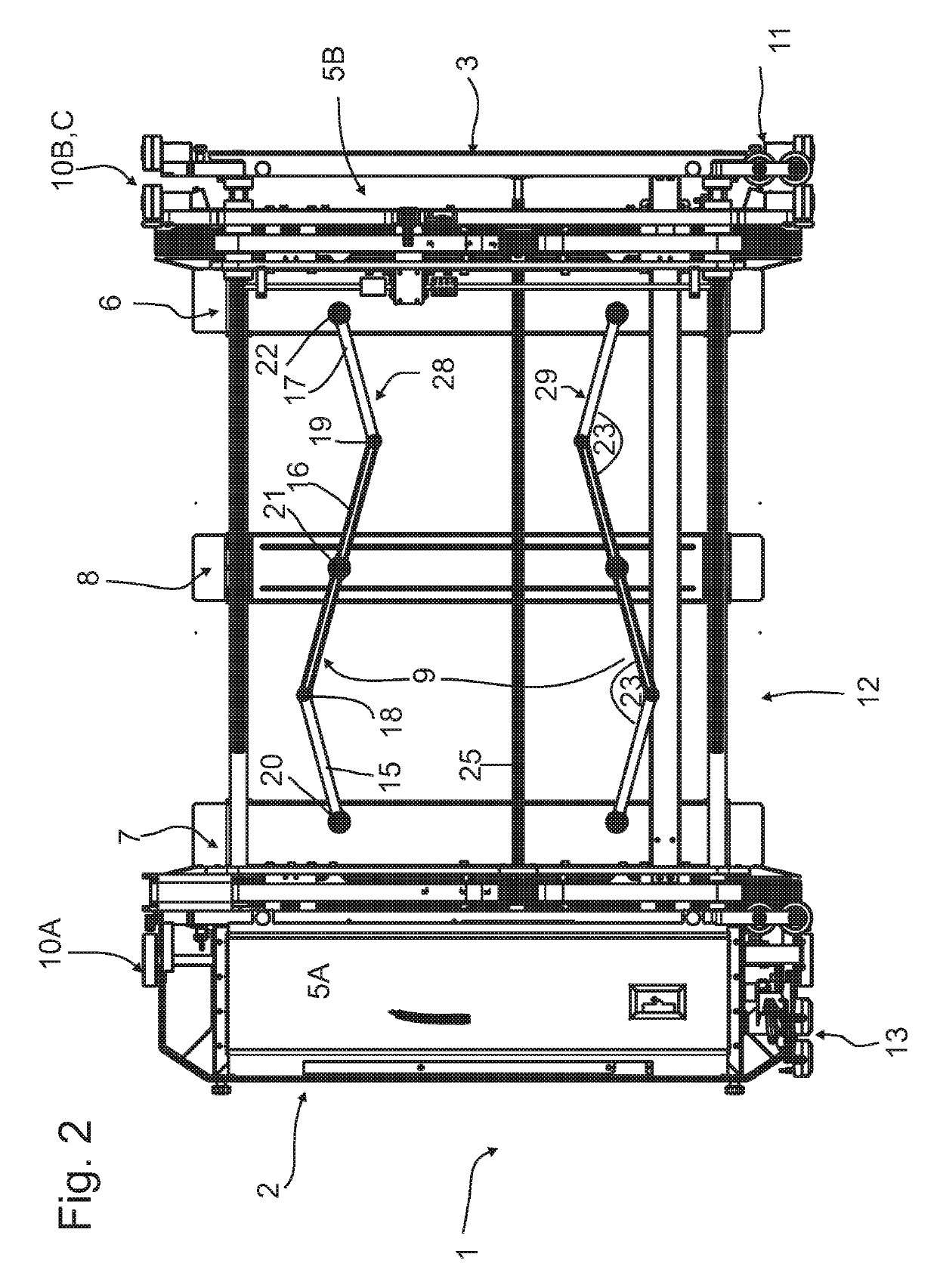
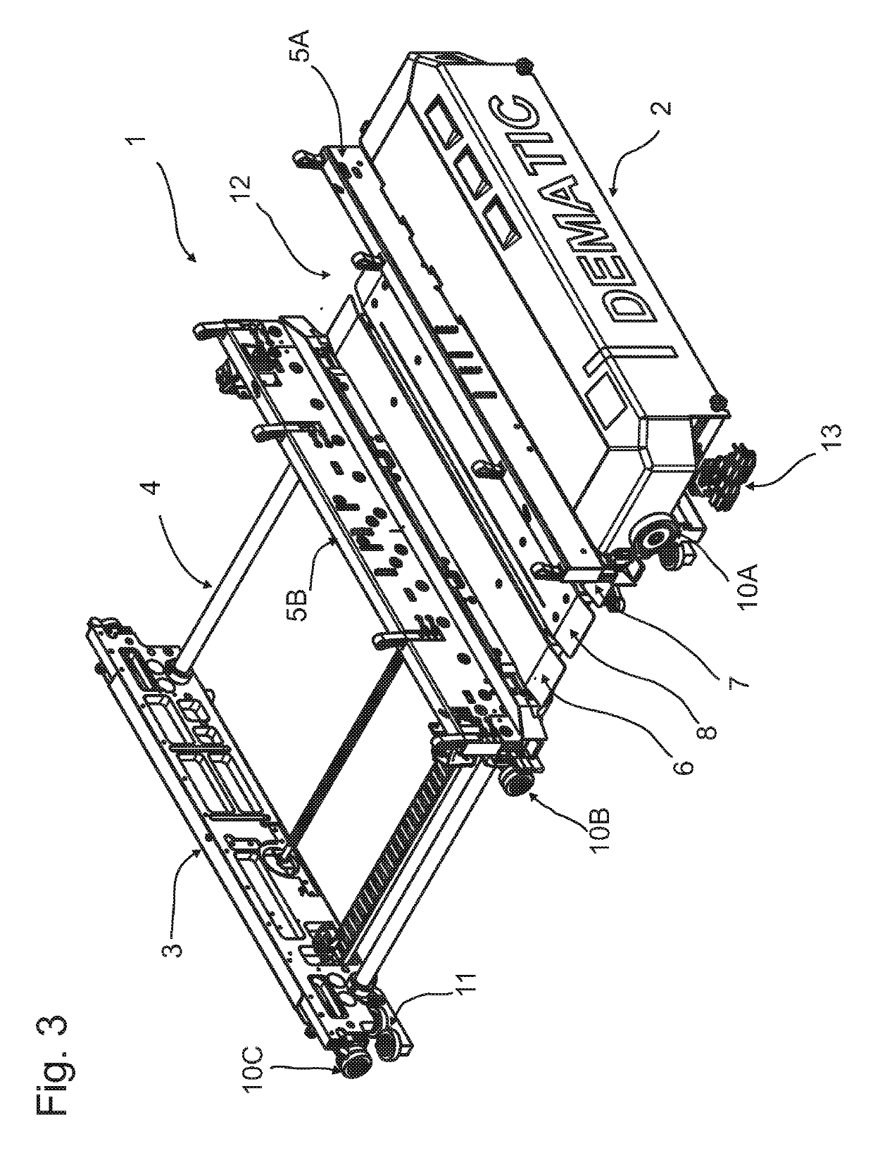
[0029]FIG. 1 shows a perspective view of a single-level rack serving apparatus or shuttle 1 having automatically centring load support, which consists of two chassis portions, namely a first chassis portion 2 and a second chassis portion 3. The two chassis halves 2 and 3 are connected to one another by way of two lateral (as seen in the direction of travel) holding rails (carrier pipes) 26 and 27 which are arranged on one vehicle side and form part of a connection structure 4, which may alternatively be referred to as a connector link.

[0030]Arranged between the chassis portions 2, 3 is a storage region 12 for receiving the load units to be transported. The storage region 12 comprises two lateral supporting plates 6 and 7 (only supporting plate 6 can be seen in FIG. 1) and a central supporting plate 8 which serve to support the load units arranged in the storage region. The supporting plates 6, 7, 8 are carried by the holding rails 26 and 27 are oriented transversely thereto. Support...


PUM


Abstract

A single-level rack serving apparatus for transporting load units, which comprises two chassis halves each having a pair of rollers and each having an extendible arm, a storage region between the chassis halves and a connection structure, wherein the chassis halves are connected to one another by the connection structure and travel on running rails by the rollers. The arms serve to pull up or push down load units onto or from the storage region which comprises at least two first and second lateral supporting plates for supportingly carrying the load units. The size of the storage region can be varied by varying the spacing between the arms together with the lateral supporting plates. A further third supporting plate is arranged between the first and second lateral supporting plates such that it supports a load unit centrally from below in the storage region irrespective of the size of the storage region.

Description

CROSS REFERENCE TO RELATED APPLICATION[0001]The present application claims priority of German patent application Ser. No. DE102016113245.4 filed Jul. 19, 2016.BACKGROUND AND FIELD OF THE INVENTION[0002]The present invention relates to a single-level rack serving apparatus, a so-called shuttle, for transporting load units.[0003]EP 2 526 032 B1 discloses a shuttle for an automated storage facility, the storage region of which extending between a first and second chassis portion. The second chassis portion can be moved relative to the first chassis portion in order to vary the storage surface. A plurality of plates overlapping in the manner of shingles form the surface of the storage region. The overlapping plates are connected via flexible bands which guarantee a maximum spaced interval and therefore ensure a relatively uniform distribution. This prevents adjacent plates from becoming separated when the spacing is increased. At the same time, the plates can move towards one another if...

Claims


Application Information

Patent Timeline
Patent Type & Authority Patents(United States)
IPC IPC(8): B65G1/04B65G1/06
CPCB65G1/0492B65G1/065
Inventor WEHNER, MATTHIASBECKER, MICHAELRECKEMEIER, HARTWIGREHM, PASCAL
Owner DEMATIC
Learn More