Electric vehicle charging connector assembly

Active Publication Date: 2019-10-01
CHENG UEI PRECISION IND CO LTD
View PDF17 Cites 15 Cited by
  • Summary
  • Abstract
  • Description
  • Claims
  • Application Information

AI Technical Summary

Benefits of technology

[0005]As described above, the plurality of the contact terminal 24 of the plug connector 2 and the plurality of the docking terminal 34 of the receptacle connector 3 are respectively assembled with the first circuit

Problems solved by technology

However, the additional independent workstation causes long working time and lots of material c

Method used


Image

  • Electric vehicle charging connector assembly
  • Electric vehicle charging connector assembly
  • Electric vehicle charging connector assembly

Examples


Example

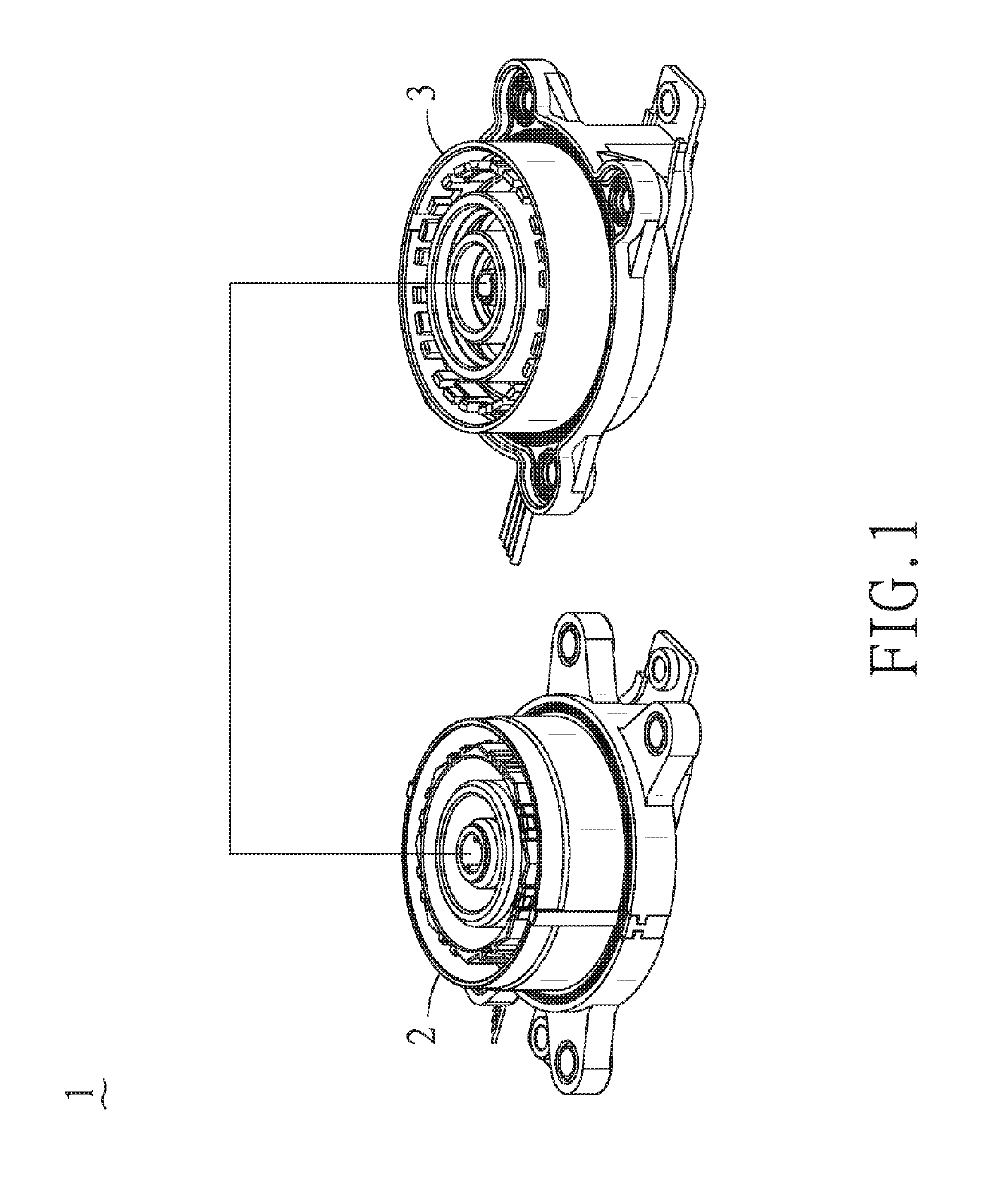
[0020]With reference to FIG. 1, an electric vehicle charging connector assembly 1 in accordance with the present invention is shown. The electric vehicle charging connector assembly 1 includes a plug connector 2 and a receptacle connector 3 docking with the plug connector 2.

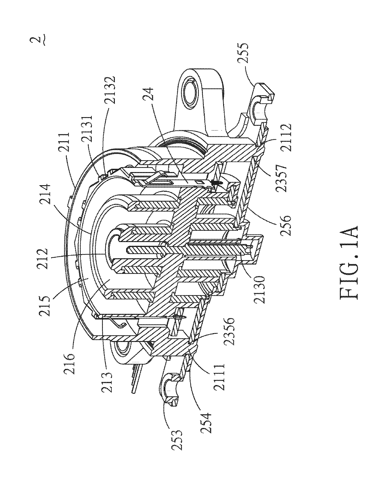
[0021]With reference to FIG. 1A, FIG. 2, FIG. 3A and FIG. 3B, the plug connector 2 configured in a charging pile of a charging station, comprises a first insulating body 21, a first circuit board 22, a plurality of contact terminals 24, a first electrode unit 2500 and a first jumper unit 25. The first insulating body 21 has a first outer ring base 211 and a first axle stand 212 extending along a center axis of the first outer ring base 211. The first axle stand 212 has a first top opening 2120. An inner wall of the first top opening 2120 protrudes inward to form a limiting pillar 2121. A first ground element 2130 is inserted in the first axle stand 212 through the first top opening 2120. The first insulating body...


PUM


Abstract

An electric vehicle charging connector assembly comprises a plug connector and a receptacle connector docking with the plug connector. The plug connector includes a first insulating body, a first circuit board, a plurality of contact terminals, a first electrode unit and a first jumper unit. The receptacle connector includes a second insulating body, a second circuit board, a plurality of docking terminals, a second electrode unit and a second jumper unit. The plurality of the contact terminal of the plug connector and the plurality of the docking terminal of the receptacle connector are respectively assembled with the first circuit board and the second circuit board in an elastically embedded manner so as to simplify manufacture procedures, capable of reducing working time and manufacturing cost as well as suitable for quantity production.

Description

BACKGROUND OF THE INVENTION1. Field of the Invention[0001]The present invention generally relates to an electrical connector assembly, and more particularly to an electric vehicle charging connector assembly.2. The Related Art[0002]As known, an electric vehicle charging connector assembly includes a plug connector configured in a charging pile of a charging station and a receptacle connector configured in an electric vehicle. To improve the charging efficiency of the electric vehicle, a kind of electric vehicle charging equipment capable of realizing large-power charge has been developed. Things that conventional electric vehicle charging connector assemblies have in common are that the plug connector and the receptacle connector have respective terminals and circuit boards used for signal transmission wherein the terminals are connected with corresponding circuit boards in a welding manner for a purpose of increasing the connection strength.[0003]In fact, as to the manufacturing pr...

Claims


Application Information

Patent Timeline
IPC IPC(8): H01R24/86H01R12/71H01R13/187H01R13/52H01R13/631H01R43/20H01R13/26H01R13/73H01R107/00
CPCB60L53/16H01R13/26H01R12/716H01R13/631H01R24/86H01R13/5202H01R43/205H01R13/187H01R2107/00H01R2201/26H01R13/73H01R12/585H01R13/245H01R13/6658H01R24/38Y02T10/70Y02T10/7072Y02T90/14
Inventor SU, YU-HUNGLEE, YUN-CHIENLIAO, JYUN
Owner CHENG UEI PRECISION IND CO LTD
Why Eureka
Try Eureka