Electric melting method for forming metal components

Inactive Publication Date: 2017-11-09
NANFANG ADDITIVE MFG TECH
View PDF27 Cites 14 Cited by
  • Summary
  • Abstract
  • Description
  • Claims
  • Application Information

AI Technical Summary

Benefits of technology

[0015]In the present invention, the edge of the formed metal component may be supported and protected by the auxiliary material or metal substrate, preventing the molten metal from overflow. The dimension and shape of the base material are matched with the shape of the initially-deposited metal layer, and the thickness thereof no less than 5 mm is preferred. The base material and deposited metal may be of same or different material. The base material may be removed in the following machining process if the base material and the deposited metal are employing different material, whereas the base material may be kept as a part of the formed metal component if the base material is employing the same material as the deposited metal.
[0016]The present invention gets rid of

Problems solved by technology

However, the formed component may cost a lot due to the fact of complex manufacturing process steps, long production cycle, low material utilization ratio.
On the other hand, complex process and great difficulty in controlling the chemical and mechanical performance also cause poor stability of quality and high defective index.
Furthermore, confined by China's manufacturing capability in the present state, the special high-performance large-scale metal component still needs importing from Japanese companies like the Japan Steel Works and the Doosan Heavy In

Method used


Image

  • Electric melting method for forming metal components
  • Electric melting method for forming metal components
  • Electric melting method for forming metal components

Examples


embodiment 1

[0038]Horizontal manufacturing for a rotary cylinder. The present embodiment illustrates a manufacturing process of cylinder by a horizontal electric melting forming method, in which the material adopted is common low-carbon steel, and the equipment used includes:

[0039](1) rotatable support platform; (2) power supply; (3) electric melting head; (4) automatic wire feeder; (5) automatic auxiliary material feeding and recycling device; (6) heater; (7) cooler; (8) base material; (9) control device (computer).

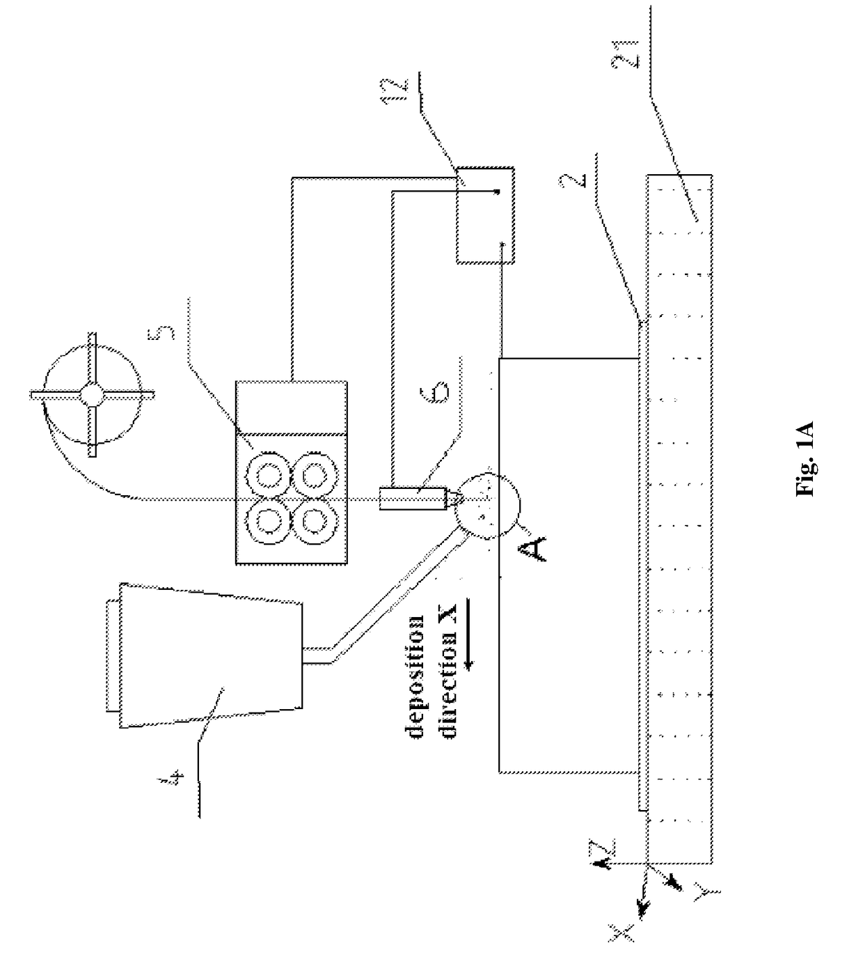
[0040]FIG. 2 is a schematic diagram illustrating the forming method of the present embodiment, in which the power supply, the automatic wire feeder and etc. are omitted for simplicity. As shown in FIG. 2, there are common low carbon steel with a diameter of 4 mm that is selected as the raw material 101; nineteen electric melting heads 401; DC power supply. In the figures, the electric melting heads are connected to the cathode of the power supply and the substrate is connected to th...

embodiment 2

[0051]Vertical manufacturing of a rotary object. An electric melting method for forming a metal component is used to vertically grow and prepare a cylindrical metal component, the equipment used in the embodiment including:

[0052](1) rotatable support platform; (2) power supply; (3) electric melting head; (4) automatic wire feeder; (5) automatic auxiliary material feeding and recycling device; (6) auxiliary material baffling device; (7) heater; (8) cooler; (9) base material; (10) control device.

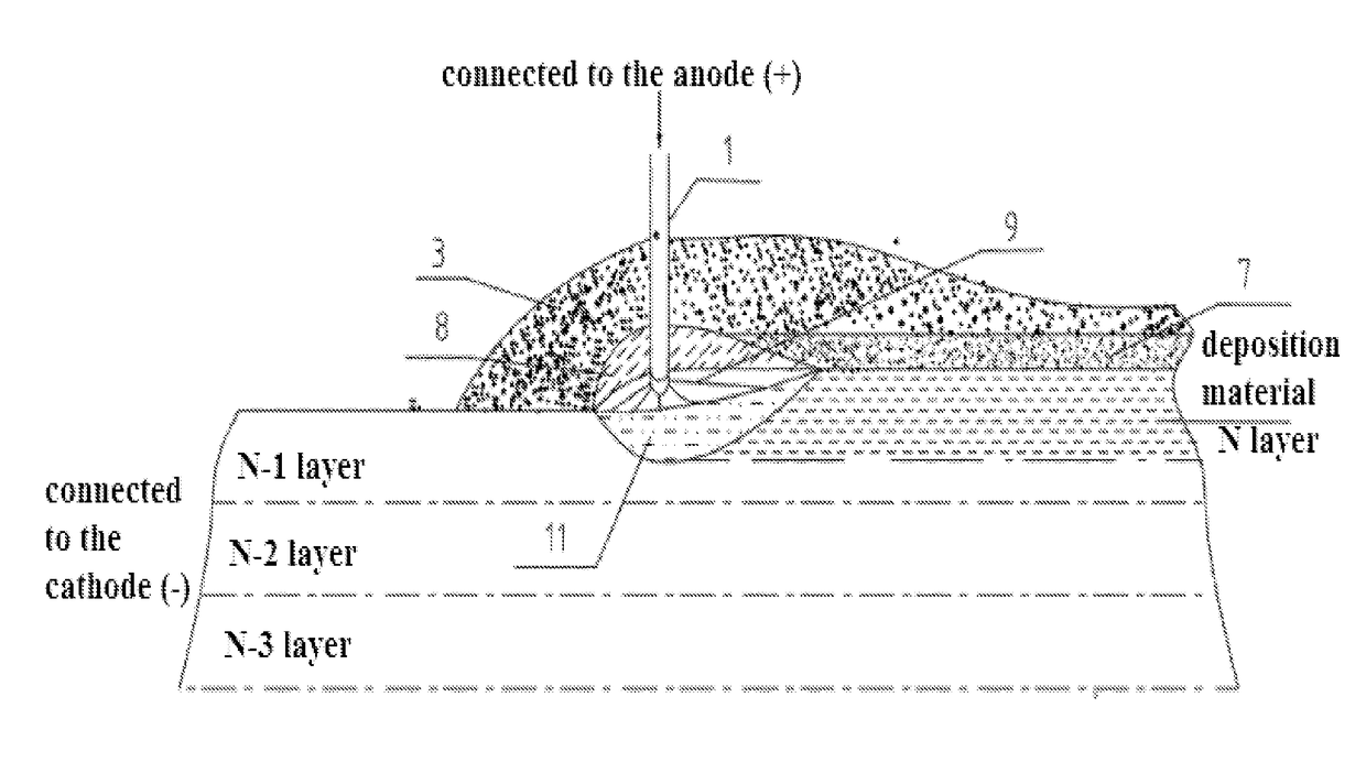
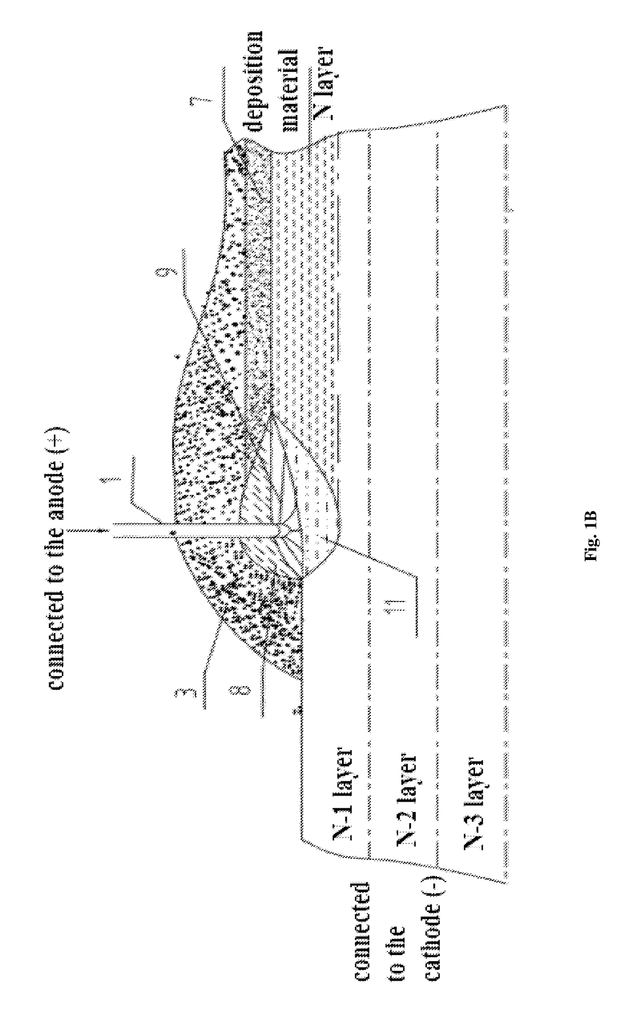
[0053]FIG. 3 is a schematic diagram illustrating the forming method of the embodiment, in which the rotatable support platform, the power supply and etc. are omitted for simplicity. As shown in FIG. 3, there are common low carbon steel with a diameter of 5 mm that is selected as the raw material; specialized auxiliary material; one electric melting head 602; DC power supply. In the figures, the electric melting head is connected to the anode of the power supply and the substrate 202 is connect...

embodiment 3

[0063]The manufacturing of the irregularly shaped workpiece. Common low-carbon steel H08 A is selected as the raw wire and an electric melting method for forming metal components is used to vertically grow and manufacture a metal component with end socket by vertical growing. The apparatus used in the embodiment including:

[0064](1) rotatable support platform; (2) power supply; (3) electric melting head; (4) automatic wire feeder; (5) automatic auxiliary material feeding device and automatic auxiliary material recycling device; (6) auxiliary material baffling device; (7) heater; (8) cooler; (9) base material; (10) control device.

[0065]FIG. 4 is a schematic illustration of the electric melting method in the present embodiment, for simplicity, the apparatus are omitted in the Fig. The selected parameters are as follows: the diameter of the wire bar is of 5 mm; the auxiliary material has 30% Fe powder added into a standard fused flux SJ101; the electric melting current is of 900 A, the ...


PUM

PropertyMeasurementUnit
Thicknessaaaaaaaaaa
Lengthaaaaaaaaaa
Speedaaaaaaaaaa

Abstract

An electric melting method for forming metal components provides an electric melting head (6) and a base material (2) being connected to the anode and the cathode of a power supply (12). During the forming of the component, the raw metal wire (1) is sent to the base material (2) and the electric melting head (6) to generate electric arc (9) between the raw wire (1) and the base material (2). The electric arc melts a part of the deposited auxiliary material (3) and creates a molten slag pool (8). Electric current generates the resistance heat and the electroslag heat. The raw wire (1) is molten under the high-energy heat resource composed of the electric arc heat, the resistance heat and the electroslag heat, and thereby creating a molten pool (11) on partial surface of the base material (2).

Description

TECHNICAL FIELD[0001]The present invention relates to electric melting methods for forming metal components.BACKGROUND OF THE INVENTION[0002]At present, modern heavy industrial equipment in fields of nuclear power, thermal power, petrochemical industry, metallurgy, shipbuilding etc. is increasingly rapidly developed towards the direction of large scale, complexity, high performance, as well as high reliability and long service life under extreme conditions. The dimension of the required key metal component such as the high-strength low-alloy steel, heat-resistance alloy or the like is becoming bigger and the quality requirement is becoming higher. In the dominated manufacturing methods, hundreds-ton great steel ingot is used for smelting and casting, and heavy forging equipment such as thousands-ton hydraulic press or the like for forge forming, and machining is followed at the last step for supplementation. Such methods may basically satisfy the quality requirement. However, the fo...

Claims


Application Information

Patent Timeline
IPC IPC(8): B29C70/82B28B1/00B05C19/04B29C64/282B29C64/153H05K3/10B29C64/295B33Y10/00B33Y30/00
CPCB29C70/82B29C64/153B29C64/295B29C64/282B33Y30/00B28B1/001H05K3/103B33Y10/00B05C19/04B23K28/02B22F10/66B22F10/25B22F12/20B22F12/10B22F12/37B22F12/55B22F2999/00B22F10/73B22F12/53B22F2202/06B23K9/04B23K9/18B23K25/005Y02P10/25
Inventor WANG, HUAMING
Owner NANFANG ADDITIVE MFG TECH
Why Eureka
Try Eureka