Supercharge Your Innovation With Domain-Expert AI Agents!

Display device

a display device and display technology, applied in the field of display devices, can solve the problems of increasing manufacturing costs, increasing manufacturing processes, and reducing yield, and achieve the effect of improving yield

Active Publication Date: 2019-10-08
JAPAN DISPLAY INC
View PDF4 Cites 4 Cited by
  • Summary
  • Abstract
  • Description
  • Claims
  • Application Information

AI Technical Summary

Benefits of technology

The invention aims to minimize the production of products using a combination of processes. This results in a higher yield, which means more products can be produced using the same methods.

Problems solved by technology

When the vapor deposition layers are divided and vapor deposited according to the colors of the emitted light to adjust the thicknesses thereof, the number of manufacturing processes increases and the yield decreases, thereby increasing manufacturing costs.

Method used

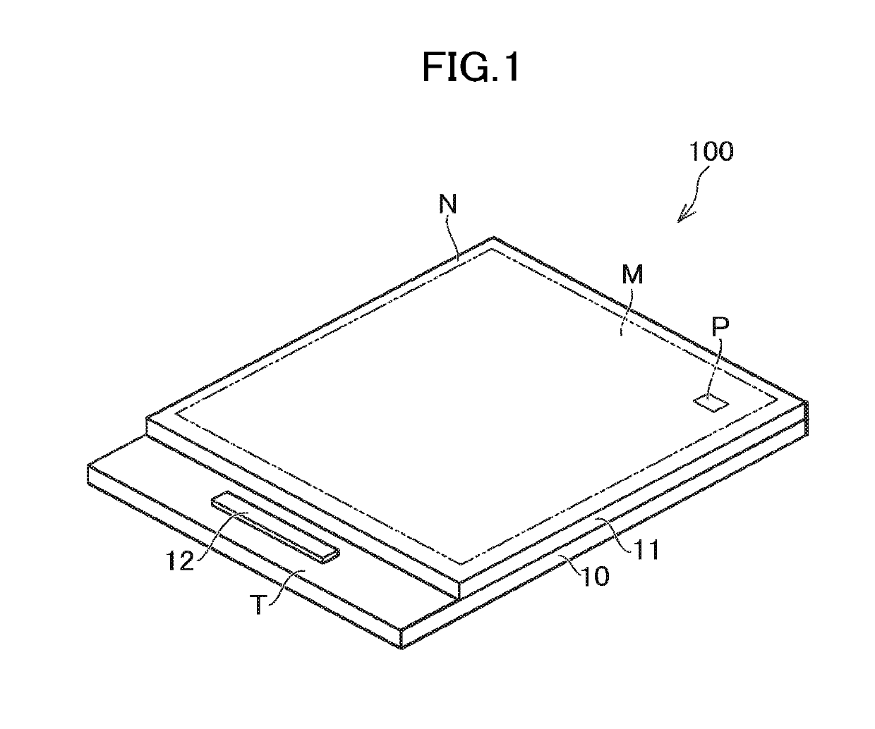
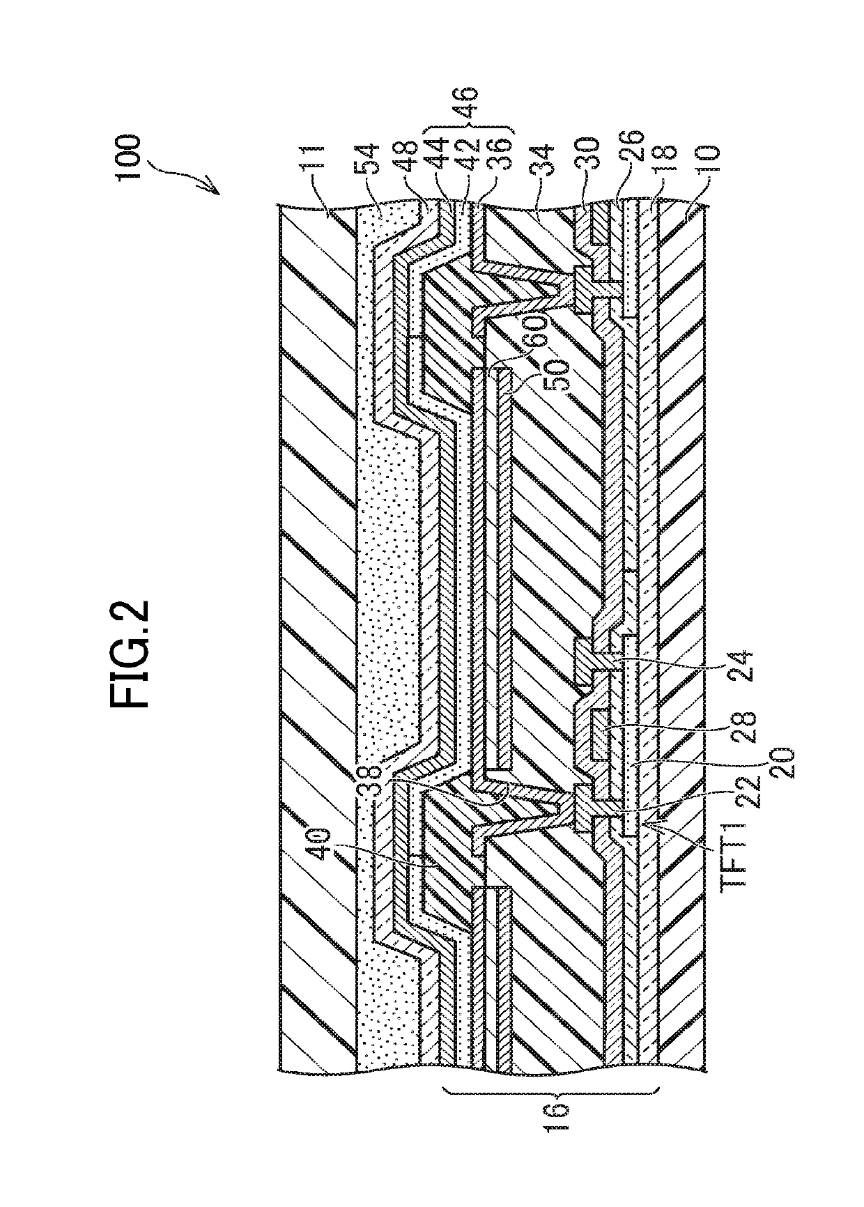
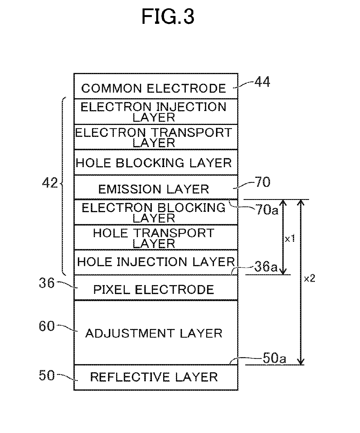

Image

  • Display device
  • Display device
  • Display device

Examples


Embodiment Construction

[0018]Hereinafter, embodiments of the present invention will be described with reference to the drawings. However, the present invention may be implemented in various forms without departing from the gist of the present invention and not be construed as being limited to the embodiments set forth herein.

[0019]For clarity, in the drawings, width, thickness, shape, and the like of each part may be schematically illustrated, when compared to an actual form thereof, but are merely examples and the present invention is not construed as being limited thereto. Same reference numerals are assigned to elements having same functions as those described and illustrated in the present specification and each drawing, and are not redundantly described herein.

[0020]Furthermore, the terms “on” and “below”, when specifying the positional relation between a component and another component in an embodiment, are not limited to the case where the component is directly on or below the other component, but ...


PUM


Abstract

A display device includes an organic electroluminescence layer including a plurality of emission layers respectively emitting light of a plurality of colors, and a reflective layer configured to reflect the light emitted from the emission layers. A shortest optical path length between the emission layers and the reflective layer is longer than at least three times of a wavelength of blue light.

Description

CROSS-REFERENCE TO RELATED APPLICATION[0001]The present application claims priority from Japanese application JP2017-187685, filed on Sep. 28, 2017, the content of which is hereby incorporated by reference into this application.BACKGROUND OF THE INVENTION1. Field of the Invention[0002]The present invention relates to a display device.2. Description of the Related Art[0003]In the related art, display devices including an organic electroluminescence layer including an emission layer are disclosed. In such a display device, light emitted from an emission layer is reflected by a reflective layer and discharged to the outside (for example, JP 2008-218328 A).[0004]In a configuration using the reflective layer as described above, by adjusting thicknesses of vapor deposition layers stacked between the emission layer and the reflective layer to form the organic electroluminescence layer, optical interference is generated and luminous efficiency and color purity are improved. When optical int...

Claims


Application Information

Patent Timeline
Patent Type & Authority Patents(United States)
IPC IPC(8): H01L33/60H01L51/50H01L51/52H01L27/32H01L27/12
CPCH01L51/5206H01L51/5221H01L51/5271H01L51/5036H01L27/124H01L27/3258H01L51/5096H01L51/5056H01L51/5092H01L51/5072H01L27/1255H10K59/35H10K59/38H10K59/124H10K59/1213H10K59/1216H10K2102/351H10K50/181H10K59/8051H10K59/878H10K59/8052H10K50/125H10K50/81H10K50/82H10K50/856H10K50/15H10K50/16H10K50/18H10K50/171
Inventor SAKAMOTO, SHIGERU
Owner JAPAN DISPLAY INC
Features
  • R&D
  • Intellectual Property
  • Life Sciences
  • Materials
  • Tech Scout
  • Unparalleled Data Quality
  • Higher Quality Content
  • 60% Fewer Hallucinations
Learn More