
Modular connector plug for high speed data transmission networks

a technology of data transmission network and connector, applied in the direction of coupling device connection, coupling device details, printed circuit aspects, etc., can solve the problems of high frequency degradation, affecting auto-negotiation, signal degradation,

Active Publication Date: 2019-10-08
BEL FUSE MACAO COMML OFFSHORE
View PDF58 Cites 0 Cited by
  • Summary
  • Abstract
  • Description
  • Claims
  • Application Information

AI Technical Summary

Benefits of technology

[0010]In another desirable aspect of the modular connector plug as disclosed herein, the phase shift and corresponding signal degradation are minimized.
[0014]In various embodiments, the inductance between cable pairs or in-plug mutual inductance may be controlled through the use of an air gap within the printed circuit board (PCB). A connector plug as disclosed herein may further physically separate the cable pairs by moving two of the four pairs to an opposing side of the connector, and / or by bringing selected cable pairs to the front of the plug so as to keep signal disruption to a minimum.

Problems solved by technology

The jacks, cable, and plug must be able to support the Ethernet protocols and may affect the auto-negotiation.
All known modular plugs that work in a wide data transmission spectra (such as from 10 to 2000 MHz) cause some degradation of the signals.
Signal degradation at high frequencies is caused by one or more of several potentially mutually dependent issues.
Introducing compensation far away from the interface may cause an unpredictable phase shift of electromagnetic signals traveling within the jack and plug connection.
The plug contact blades have high intrinsic self-inductance and uncontrolled and relatively low capacitance between adjacent contacts.
Known designs also do not allow for control of the interaction of the cable pairs within the plug.
The distance between the cable terminations and the contacts is overly long in existing designs.
Finally, most of the existing plug designs attempt to provide easy termination in the field at the expense of transmission performance.

Method used


Image

  • Modular connector plug for high speed data transmission networks
  • Modular connector plug for high speed data transmission networks
  • Modular connector plug for high speed data transmission networks

Examples


third embodiment

[0105]With regard to FIGS. 20-29, a modular connector plug 300 is shown. The PCB 302 includes a first row of vias 308a and a second row of vias 308b. The first row of vias 308a is closer to the contact end 304 than the cable end 306 of the PCB 302. In this configuration (as shown in FIGS. 21-23), each of the plug contacts 324 includes a first end 326, a second end 328, and an intermediate post 348 connected to the bridge portion 332 between the first end and the second end. Each of the respective plug contacts 324a-324h are identical except for the inclusion of a protrusion Pc on plug contact 324c, a protrusion Pd on plug contact 324d, a protrusion Pf on plug contact 324f, and a protrusion Pg on plug contact 324g.

[0106]In such an embodiment the distance between the jack-plug contact interface and the capacitor formed between contacts is very short, resulting in negligible self-inductance and phase shift. All of the contacts 324 may further have approximately the same length as bein...

fourth embodiment

[0111]Turning now to FIGS. 30-33, a modular connector plug 400 is shown. The modular connector plug 400 includes a PCB 402 defining a plurality of contact holes 408 therein. As shown in FIGS. 31-33, each of a plurality of contact blades 450 include a respective plug portion 452 inserted in a respective contact hole 408. The contact blades 450 may be identical in various exemplary embodiments of the connector plug 400. Each contact blade 450 further includes an insulation piercing protrusion 454 opposite the plug portion 452. The connector plug 400 also includes a capacitance defined within the PCB 402 between each pair of adjacent contact holes 408. Each capacitance is defined by a first electrode 458 disposed on the PCB 402 in association with one contact hole 408 and a second electrode 460 for example disposed in association with an adjacent contact hole, and a dielectric 456 associated with an intervening portion of the PCB. Each contact hole 408 is a plated through hole in elect...


PUM


Abstract

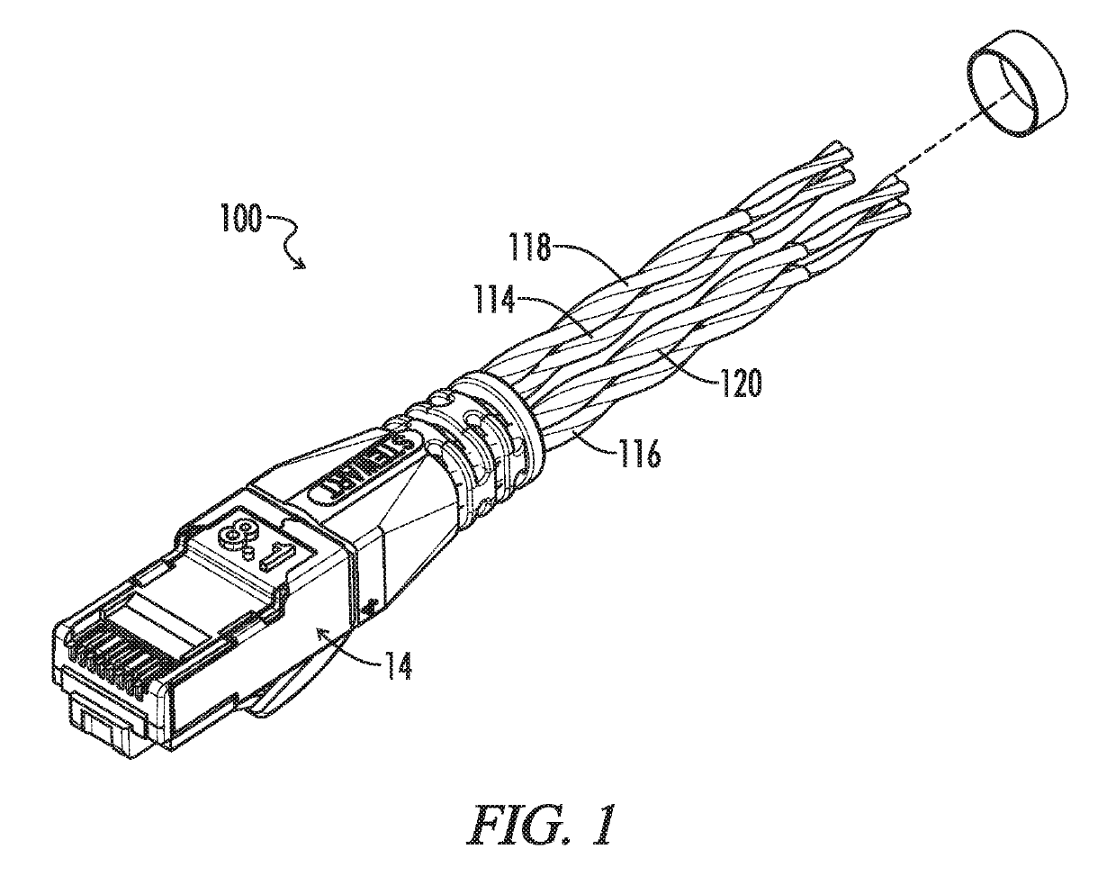
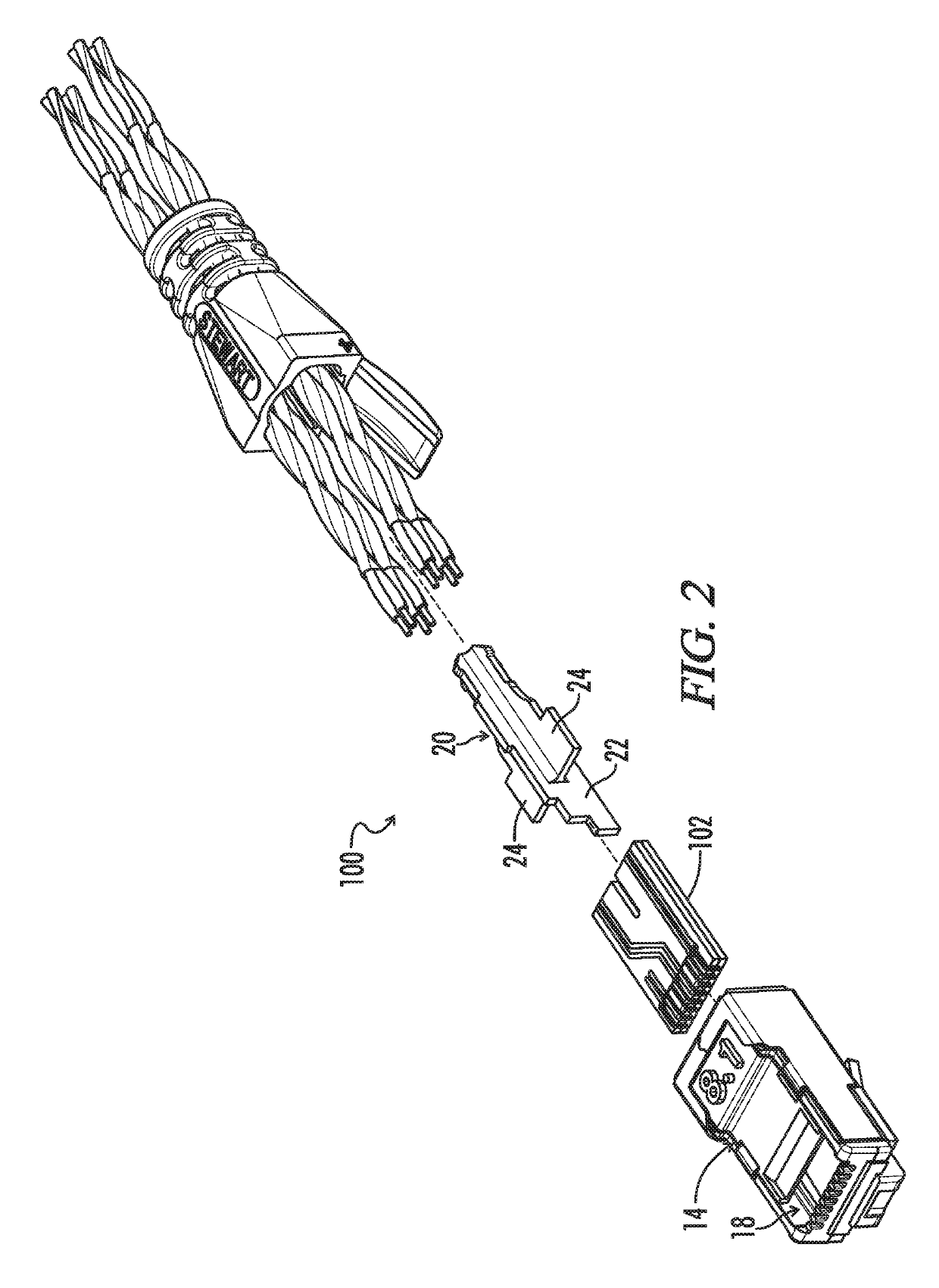
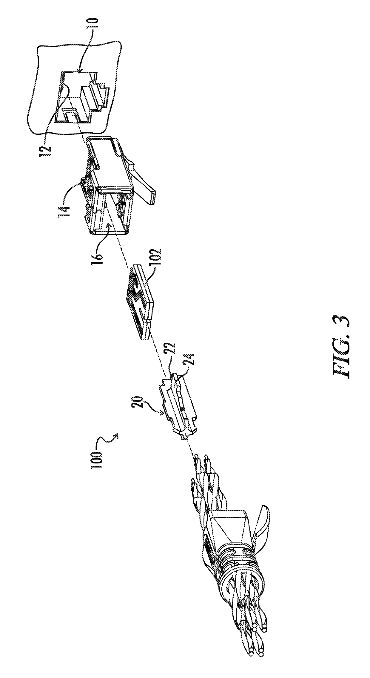
A modular connector plug includes controlled capacitances to compensate for near end cross talk at the connector interface created by interaction of signals having signal frequencies in a data transmission bandwidth. A printed circuit board (PCB) is configured to receive cable pairs, and a connector assembly includes first and fourth plug contacts corresponding to the first cable pair and second and third plug contacts corresponding to the second cable pair. First ends of each contact are connected to the PCB, and second ends extend in parallel with each other and transversely to the PCB length, collectively defining a contact interface proximate the contact end. Each contact has a maximum width at the contact interface, with at least one plug contact having a maximum width greater than the maximum width of another plug contact. Each contact accordingly defines an electrode of a compensating capacitance formed between adjacent pairs of plug contacts.

Description

CROSS-REFERENCES TO RELATED APPLICATIONS[0001]This application is a continuation of International Patent Application No. PCT / US2016 / 043334, filed Jul. 21, 2016, and further claims priority of U.S. Provisional Patent Application No. 62 / 195,062, filed Jul. 21, 2015, and which is hereby incorporated by reference.[0002]A portion of the disclosure of this patent document contains material that is subject to copyright protection. The copyright owner has no objection to the reproduction of the patent document or the patent disclosure, as it appears in the U.S. Patent and Trademark Office patent file or records, but otherwise reserves all copyright rights whatsoever.BACKGROUND[0003]The present invention relates generally to a modular plug for data transmission. More particularly, the present invention relates to a modular plug for high speed data transmission in support of multi-gigabit Ethernet protocols.[0004]The use of modular plugs and jacks for data transmission is known. Plugs are att...

Claims


Application Information

Patent Timeline
Patent Type & Authority Patents(United States)
IPC IPC(8): H01R13/6466H05K1/02H01R13/66H01R24/64H01R24/28H01R13/6463H05K1/11
CPCH01R13/6463H05K1/0228H01R13/665H01R13/6466H01R24/28H05K1/0245H01R24/64H05K1/117H05K2201/09063H05K2201/10356H05K2201/10295
Inventor MAROWSKY, RICHARD D.BELOPOLSKY, YAKOVGUTTER, DAVID H.
Owner BEL FUSE MACAO COMML OFFSHORE
Learn More