RFID Chip Employing An Air Gap Buffer

a technology of air gap buffer and rfid chip, which is applied in the field of radio frequency identification (rfid) tags, can solve the problems of poor electromagnetic characteristics of rfid tags for the transmission of signals using common rfid operational frequencies, and the rfid tags can suffer from significant rf signal degradation, so as to reduce the degree of signal degradation caused by the proximity of the surface, the effect of reducing the rf signal degradation

Active Publication Date: 2013-01-17
GEORGE SCHMITT & CO
View PDF4 Cites 0 Cited by
  • Summary
  • Abstract
  • Description
  • Claims
  • Application Information

AI Technical Summary

Benefits of technology

[0007]It is an object of the invention to provide an RFID tag designed to minimize RF signal degradation due to proximity to a mounting surface. The RFID tag is formed such that the RFID inlay portion of the tag is held away from the surface to which the tag is affixed. This arrangement has the advantage of creating a gap between the RFID transponder antenna and the mounting surface such that the degree of degradation caused to the signal from the proximity of the surface is reduced.

Problems solved by technology

Anything interfering with RF signals in the area can create a problem that must be addressed.
RFID tags can suffer from significant RF signal degradation when placed in proximity to a material.
Unfortunately, many materials to which it would be desirable to attach an RFID tag have poor electromagnetic characteristics for the transmission of signals using common RFID operational frequencies.

Method used


Image

  • RFID Chip Employing An Air Gap Buffer
  • RFID Chip Employing An Air Gap Buffer
  • RFID Chip Employing An Air Gap Buffer

Examples


Embodiment Construction

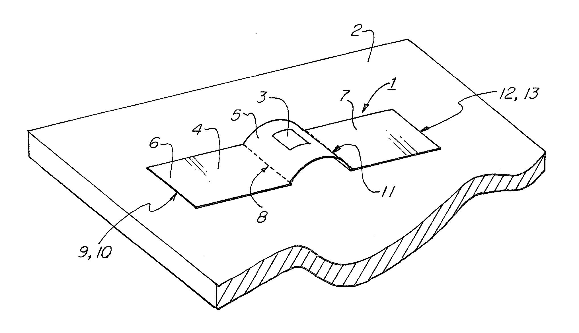
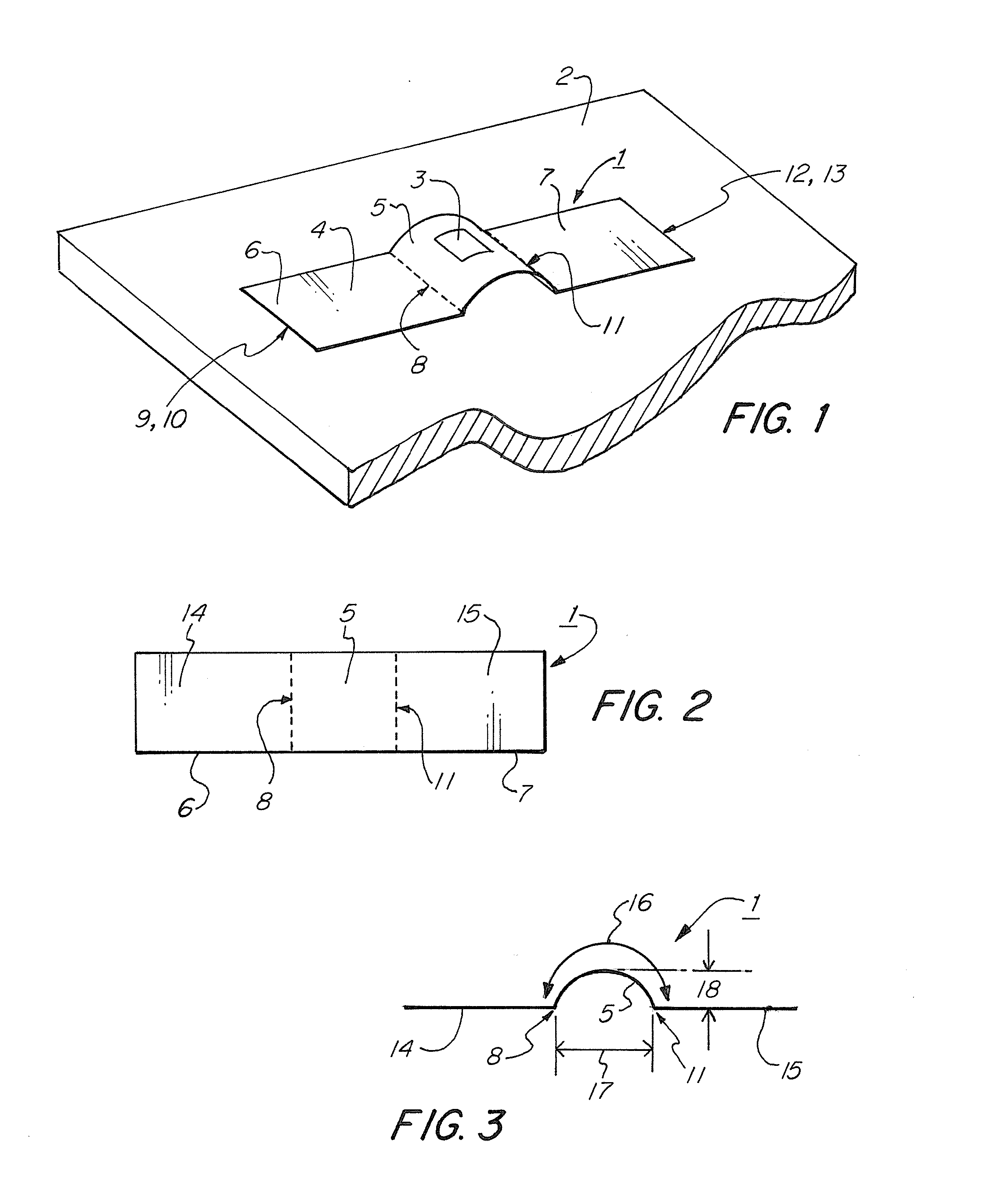
[0020]FIG. 1 illustrates an overview of a RFID tag 1 affixed to a mounting surface 2, according to an embodiment of the invention. RFID tag 1 comprises an RFID inlay 3, and mounting strip 4. RFID inlay 3 may comprise a radio transponder, antenna, power source, microprocessor, and / or storage space, which together are adapted to receive a radio frequency signal from an RFID reader (not shown) and respond with a radio frequency signal containing information. RFID inlay 3 may be attached, laminated, incorporated into, or otherwise conformed to mounting strip 4 in a suitable manner. Mounting strip 4 may comprise a plastic, paper, composite, laminar, or other suitable material for affixing objects. In alternative embodiments, mounting strip 4 may comprise, in whole or in part, a tamper-evident material (not shown). Mounting strip 4 comprises central portion 5, first side portion 6, and second side portion 7. First side portion 6 has a first inner end 8 disposed toward the central portion ...


PUM

PropertyMeasurementUnit
radio frequencyaaaaaaaaaa
lengthaaaaaaaaaa
frequencyaaaaaaaaaa

Abstract

An RFID tag incorporating an arched buffer such that the RFID inlay containing the RFID transponder is held away from the mounting surface. This has the advantage of reducing RF signal degradation caused by the electromagnetic properties of the material.

Description

CROSS-REFERENCE TO RELATED APPLICATIONS [0001]This application claims the benefit, under 35 U.S.C. §119 (e), of Provisional Patent Application Ser. No. 61 / 506,457 filed Jul. 11, 2011, the content of which is hereby incorporated by reference in its entirety.FIELD OF THE INVENTION [0002]This invention relates to radio frequency identification (RFID) tags.BACKGROUND OF THE INVENTION [0003]Radio Frequency Identification (“RFID”) is a technology for identifying or receiving information about physical objects from a distance using a small radio transponder. The components of the radio transponder, including any microprocessor or antenna, can be incorporated into an RFID inlay. An RFID inlay is typically packaged into an RFID tag to be attached to the surface of the object. Applications of this technology include retail inventory control, package and baggage tracking, authentication and security, and so forth.[0004]An RFID reader is used to communicate with an RFID tag using radio frequenc...

Claims


Application Information

Patent Timeline
Patent Type & Authority Applications(United States)
IPC IPC(8): G06K19/067B32B37/12B32B37/14B23P11/00
CPCY10T29/49817G06K19/041Y10T29/49826
Inventor GUNTHER, WILLIAM G.
Owner GEORGE SCHMITT & CO
Why Eureka
Try Eureka