Detachable tray for a ladder

a technology of ladders and trays, applied in the field of ladders, can solve the problems of increased risk, high cost, high labor intensity, and limited access to supplies by people, and achieve the effects of convenient loading and unloading of equipment, convenient transportation, and low cost of manufactur

Active Publication Date: 2019-10-15
JOHNSEN ERIC
View PDF4 Cites 1 Cited by
  • Summary
  • Abstract
  • Description
  • Claims
  • Application Information

AI Technical Summary

Benefits of technology

[0015]It is yet another object of the present invention to provide a tray as described above that secures to ladders in a highly stable fashion.
[0016]It is still another object of the present invention to provide a tray as described above that is easy to load with equipment and effortless to transport.
[0017]It is yet still another object of the present invention to provide a tray as described above that is limited in parts, inexpensive to manufacture, and simple to use.

Problems solved by technology

When positioned on a ladder to perform a particular task, a person typically has limited accessibility to supplies, such as tools or materials.
As such, a person is required to repeatedly climb up and down the ladder in order to access supplies from the toolbox that are needed to accomplish the particular task, which is both highly inefficient and labor intensive.
Furthermore, repeatedly climbing up and down a ladder, especially while carrying multiple items, introduces an increased risk of falling, which can result in serious injury.
However, it has been found that these types of tool retaining articles are somewhat uncomfortable to wear and significantly limit the number and size of tools that a worker can hold at any one time.
These tool retaining articles may also cause the wearer to move into awkward positions to retrieve the tools, which can increase the risk of falling and experiencing serious injury.
When mounted, the ladder tray extends out from one side of the ladder and does not prevent a user from climbing up or down the ladder.
As a first drawback, ladder trays of the type as described in the '148 patent are incapable of being disposed on a flat surface while loaded with the various instruments due to its inverted L-shaped configuration.
Subsequent thereto, the user would be required to climb up and down the ladder to retrieve the tools to be held by the tray, which is highly time-consuming and labor-intensive.
This drawback also introduces additional hazards to the user, who may have to carry one or more items while simultaneously climbing up and down the ladder, often multiple times, thereby increasing the risk of falling and experiencing significant injury.
It also requires that the various tools to be retained by the tray are removed therefrom between uses (e.g., when stored on a truck), thereby rendering the user less ready to perform a future task.
As a second drawback, ladder trays of the type described in the '148 patent are not designed to retain larger items, such as automated drills, nail guns and the like.
As a result, routinely used items which are relatively large in size are only able to be disposed flat on the relatively small and shallow shelf in an unbalanced manner.
As a third drawback, ladder trays of the type as described in the '148 patent are not typically provided with a handle and, as such, are relatively difficult to carry when transporting up and down a ladder.
As a fourth drawback, ladder trays of the type as described in the '148 patent are typically designed for use with a particular size and shape of ladder.
In particular, the portion of the ladder tray that directly engages the ladder is typically rigid and dimensionally fixed in construction and is therefore incapable of being adjusted to accommodate ladders of varying rail widths.
As a fifth drawback, ladder trays of the type as described in the '148 patent are often secured to ladders in a relatively unstable fashion.
For instance, as noted above, the inability to adjust conventional ladder trays to fittingly mount on ladders of varying dimensions and different rail configurations often renders the ladder tray unstable and unreliable as a support structure.
Additionally, conventional ladder trays that are designed to hook onto one or more ladder rungs often fail to restrict lateral and / or rotational movement of the tray.
As can be appreciated, limited lateral and / or rotational movement of the tray relative to the ladder can cause equipment on the tray, or the tray itself, to fall, creating a potentially dangerous condition.

Method used


Image

  • Detachable tray for a ladder
  • Detachable tray for a ladder
  • Detachable tray for a ladder

Examples


Embodiment Construction

Construction of Tray 11

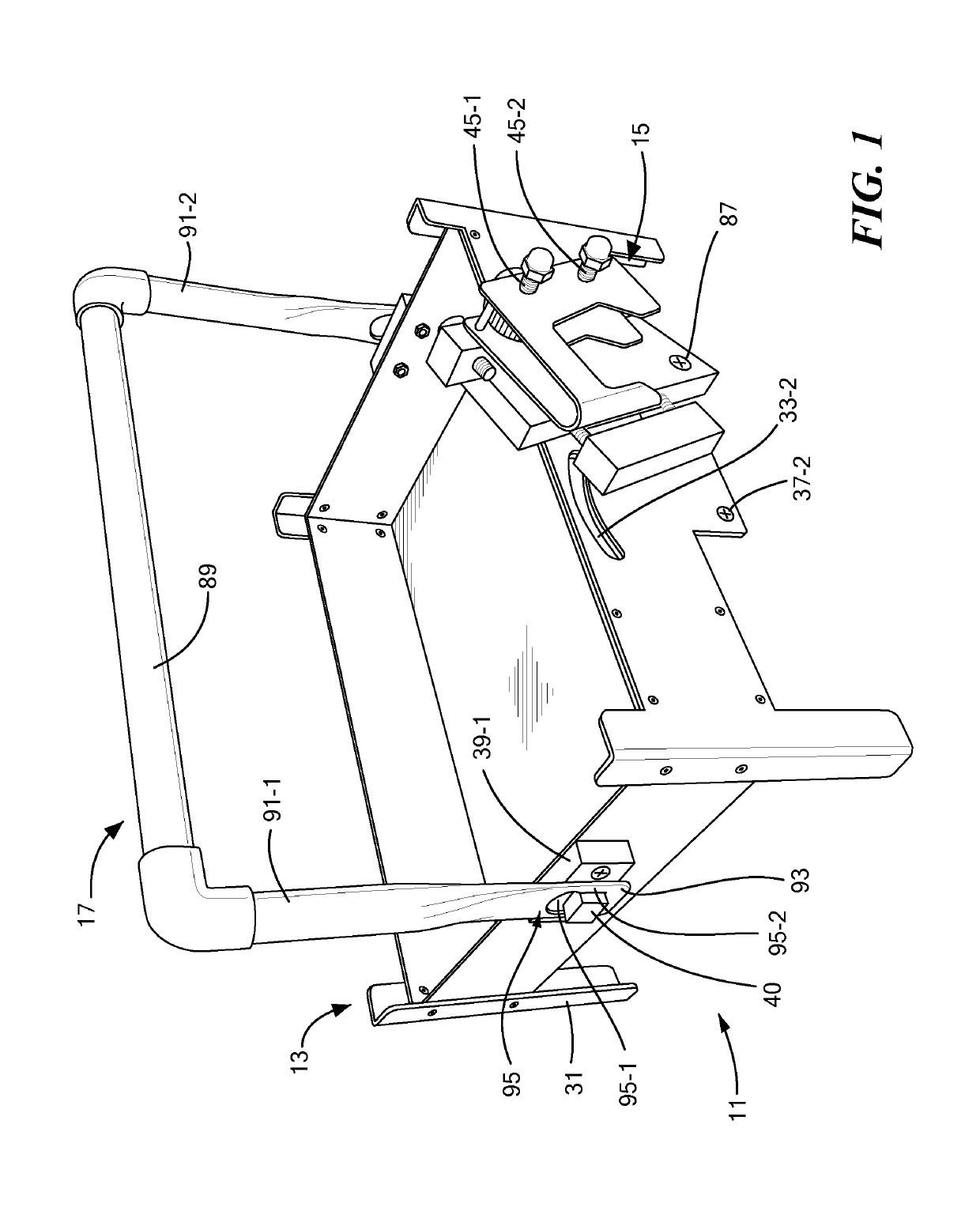
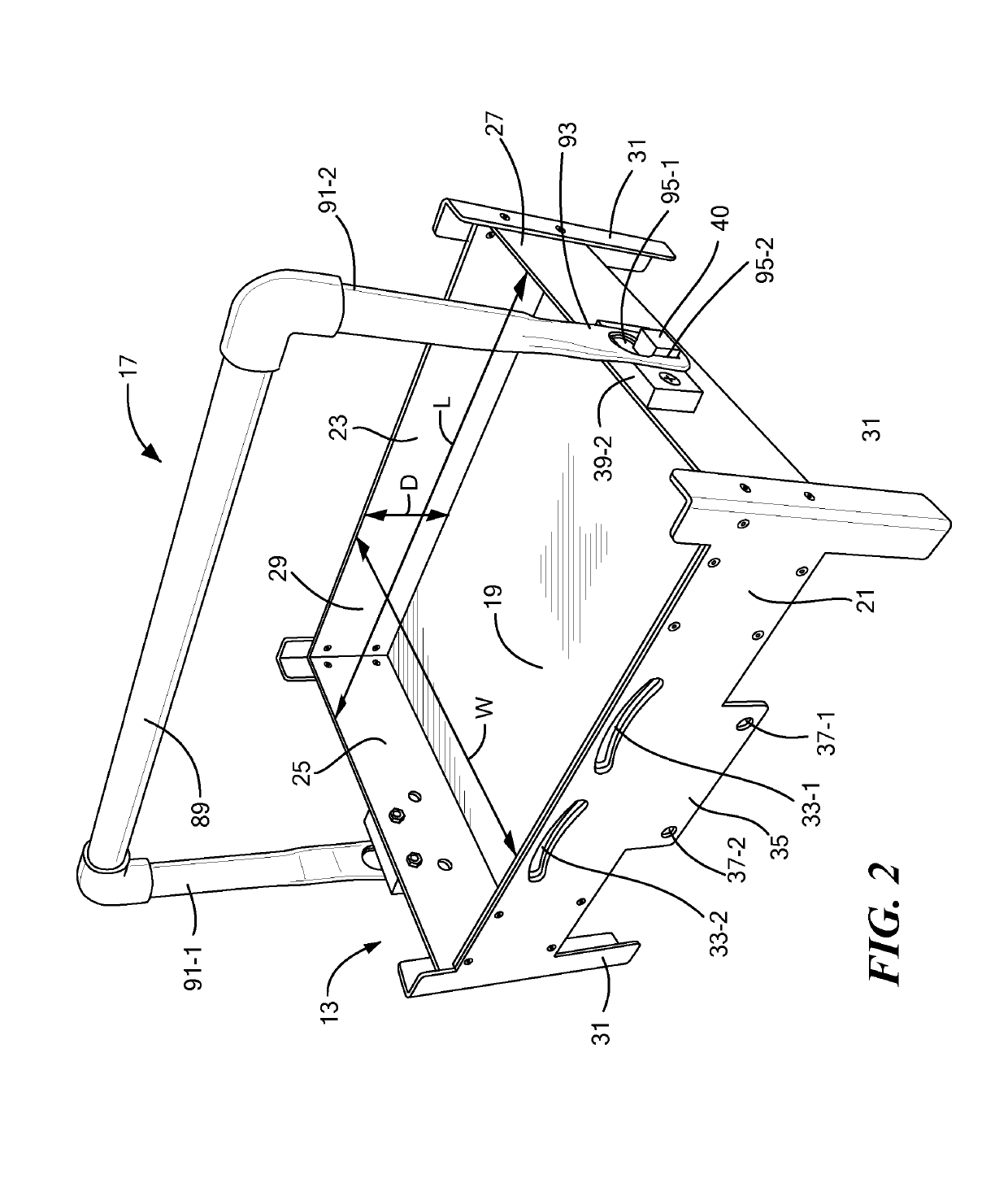
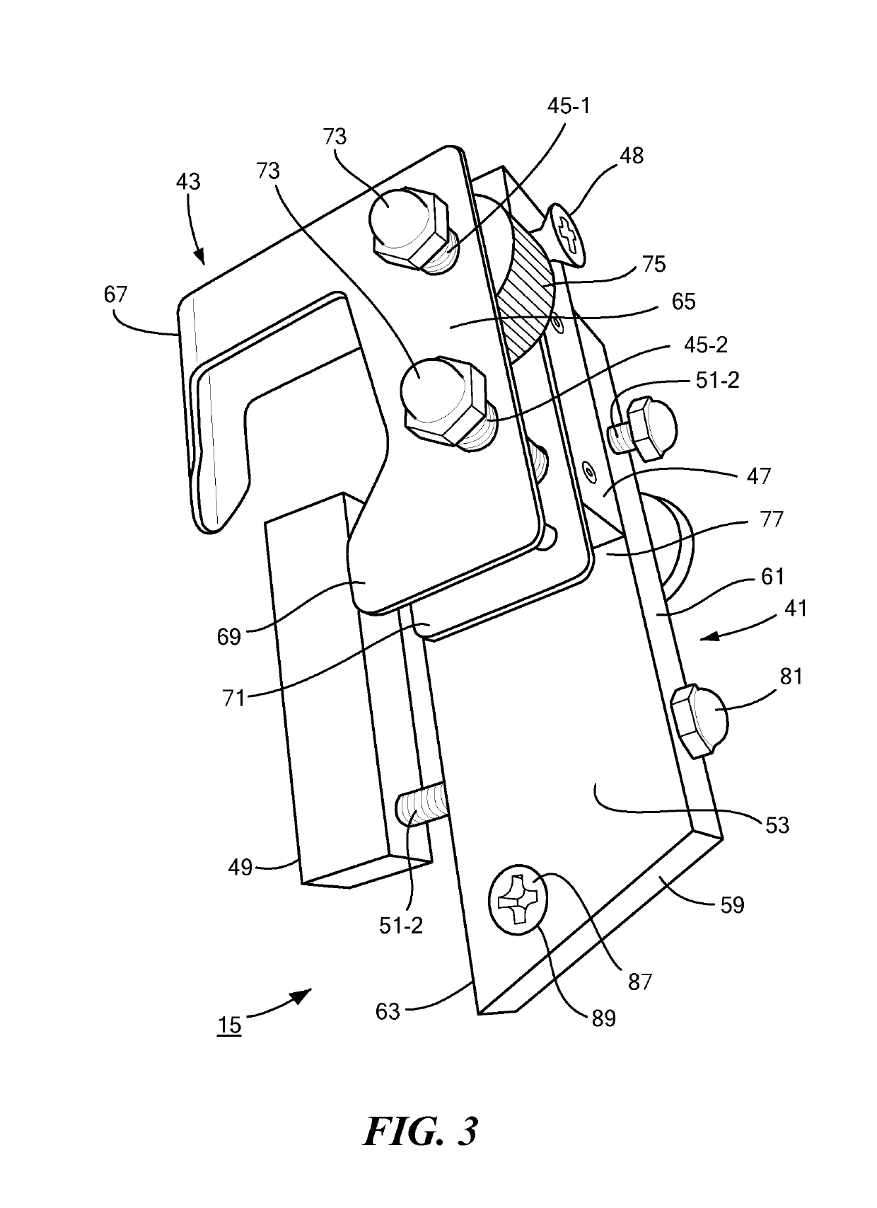
[0026]Referring now to FIG. 1, there is shown a front perspective view of a tray for retaining supplies, the tray being constructed according to the teachings of the present invention and identified generally by reference numeral 11. As will be described in greater detail below, tray 11 is designed to be removably mounted onto a conventional ladder in a simple and efficient manner, thereby providing a user positioned on the ladder with readily available access to the supplies collected thereon. As a principal feature of the present invention, tray 11 can be adjusted, as needed, to allow for its reliable and stable securement to a wide variety of different ladder shapes and styles.

[0027]As defined herein, use of the term “supplies” denotes any tool or material that is commonly utilized by a worker disposed on a ladder. Specific examples of supplies which may be retained by tray 11 include, but are not limited to, paint products, paint tools, hand tools, power t...


PUM


Abstract

A detachable tray for a ladder includes a container for retaining supplies, a bracket assembly pivotally coupled to the container that is adapted to be releasably secured to the ladder, and a handle pivotally connected to the container to facilitate tray transport. The bracket assembly includes a rung engaging bracket that is movably connected to a base by a pair of transverse threaded members. A gap is defined between the bracket and the base that is dimensioned to fittingly receive one side rail of the ladder, the width of the gap being adjustable to accommodate side rails of varying widths. A support block is slidably coupled to a side of the base by a pair of posts. Together, the base and the support block apply a firm abutment force against the opposite side of the side rail than the bracket, thereby stabilizing the tray in place on the ladder.

Description

FIELD OF THE INVENTION[0001]The present invention relates generally to ladders and more particularly to trays that are adapted to be detachably mounted onto ladders.BACKGROUND OF THE INVENTION[0002]Ladders are commonly utilized in a variety of industries, such as painting and roofing, to provide access to an area at a considerable height. An extension ladder is one well-known type of ladder that includes a pair of parallel side rails interconnected by a plurality of transverse rungs. In use, a person disposes the bottom of the extension ladder on the ground and angles the top of the extension ladder against a support structure, such as a house. The person is then able to climb the ladder by sequentially stepping on the plurality of transverse rungs and thereby perform a particular task at a significant height above the ground.[0003]When positioned on a ladder to perform a particular task, a person typically has limited accessibility to supplies, such as tools or materials. Rather, s...

Claims


Application Information

Patent Timeline
Patent Type & Authority Patents(United States)
IPC IPC(8): E06C7/14
Inventor JOHNSEN, ERIC
Owner JOHNSEN ERIC
Why Eureka
Try Eureka