Wavelength conversion laser light source, and image display device

a laser light source and wavelength conversion technology, applied in non-linear optics, instruments, optical elements, etc., can solve the problems of not being able to achieve direct polarized light, not being able to ensure that the light emitted from the solid laser medium is directly polarized light, and not being able to achieve the light output that should be achieved according to the design. achieve the effect of high output and stable fashion

Active Publication Date: 2015-10-27
PANASONIC INTELLECTUAL PROPERTY MANAGEMENT CO LTD
View PDF23 Cites 0 Cited by
  • Summary
  • Abstract
  • Description
  • Claims
  • Application Information

AI Technical Summary

Benefits of technology

[0026]The object of the present invention is to provide a wavelength conversion laser light source and an image display device which is capable of outputting a second harmonic wave after wavelength conversion, at high output and in a stable fashion, even in cases where a wavelength plate is inserted into the laser resonator.
[0029]According the present invention, even if a wavelength plate is inserted into the laser resonator, it is possible to output the second harmonic wave after wavelength conversion, at a high output and in a stable fashion.

Problems solved by technology

However, with an isotropic monocrystalline material, such as Nd:YAG, or a ceramic laser medium, even if the axial orientation of the solid laser medium is selected, it is not possible to ensure that the light emitted from the solid laser medium is directly polarized light.
In this way, in a YAG crystal or a solid laser medium using ceramic material, since there is no optical anisotropy, it is not possible to obtain directly polarized light if the composition shown in FIG. 13 is used directly without modification.
However, it is known that, if a wavelength plate is inserted into the resonator in order to stabilize the output from the wavelength conversion laser light source, and if the input pump light is made large in order to raise the light output from the wavelength conversion laser light source, as in the prior art example described above, then problems occur in that the light output that ought to be achieved according to the design is not obtained, or the light output becomes instable.
More specifically, it is clear that the effect of stabilizing output is not sufficient if the contents of the prior art example described above are simply implemented directly.

Method used


Image

  • Wavelength conversion laser light source, and image display device
  • Wavelength conversion laser light source, and image display device
  • Wavelength conversion laser light source, and image display device

Examples


first embodiment

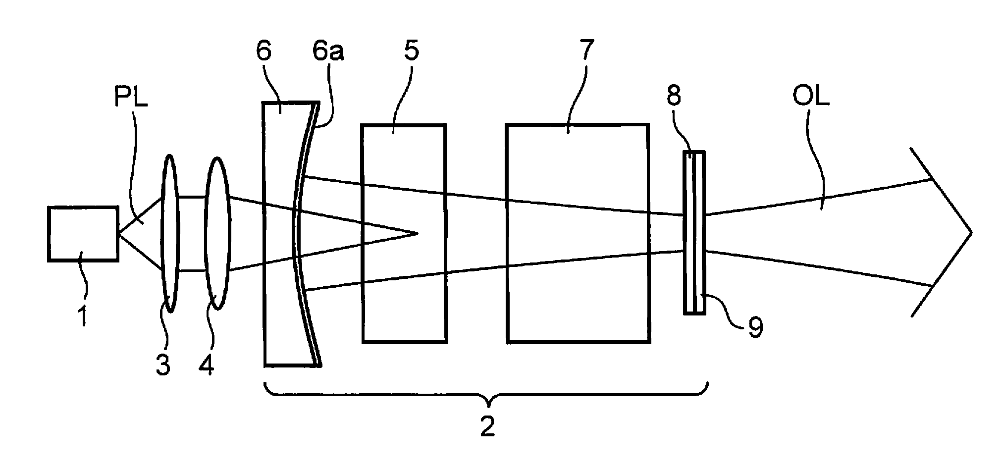
[0049]FIG. 1 is a schematic drawing showing the composition of a wavelength conversion laser light source according to a first embodiment of the present invention. The wavelength conversion laser light source shown in FIG. 1 includes: a pump light source 1, a collimating lens 3, a condensing lens 4, a solid laser medium 5, a concave mirror 6, a wavelength conversion element 7, a λ / 4 wavelength plate 8 and an optical film 9.

[0050]The wavelength conversion laser light source shown in FIG. 1 is an end-pumped type of laser light source in which pump light is input from an end face of the laser medium. The pump light PL is generated by the pump light source 1, is converted into parallel light by the collimating lens 3, and is then condensed into the solid laser medium 5 arranged inside the laser resonator 2 by the condensing lens 4.

[0051]The laser resonator 2 includes a solid laser medium 5 and a wavelength conversion element 7, and an isotropic monocrystalline material or ceramic laser ...

second embodiment

[0074]Next, a second embodiment of the invention will be described. FIG. 6 is a schematic drawing showing the composition of a wavelength conversion laser light source according to a second embodiment of the present invention. The wavelength conversion laser light source shown in FIG. 6 includes: a pump light source 1, a collimating lens 3, a condensing lens 4, a solid laser medium 5, a concave mirror 6, a wavelength conversion element 7, a λ / 4 wavelength plate 8, an optical film 9 and cooling sections 10a and 10b.

[0075]The pump light PL is generated by the pump light source 1, is converted into parallel light by the collimating lens 3, and is then condensed into the solid laser medium 5 arranged inside the laser resonator 2a by the condensing lens 4. The laser resonator 2a includes a solid laser medium 5 and a wavelength conversion element 7, and monocrystalline Nd:YAG material or an optical ceramic material having a garnet structure, such as Nd:YAG, is used as the material of the...

third embodiment

[0102]Next, a third embodiment of the invention will be described. The present embodiment is a first image display device which adapts the wavelength conversion laser light source according to the first or second embodiment. FIG. 11 is a schematic drawing showing a composition of a laser projector device which uses a wavelength conversion laser light source according to the first or second embodiment of the present invention.

[0103]The laser projector device 1200 shown in FIG. 11 is a laser projector which uses a ferroelectric LCOS (Liquid Crystal On Silicon), and a wavelength conversion laser light source according to the first or second embodiment described above is used for a green laser light source 1201g.

[0104]As shown in FIG. 11, the laser light emitted from a blue laser light source 1201b, a red laser light source 1201r and a green laser light source 1201g is collimated into parallel light by collimating lenses 1202r, 1202g and 1202b. Mirrors 1203r, 1203g, and 1203b are diele...


PUM

PropertyMeasurementUnit
resistivityaaaaaaaaaa
wavelengthaaaaaaaaaa

Abstract

A wavelength conversion laser light source, includes: a solid laser medium; a wavelength conversion element; a concave mirror on which a first reflecting surface reflecting a fundamental light wave and a the second harmonic light wave is formed; and a wavelength plate on which a second reflecting surface reflecting the fundamental light wave and transmitting the second harmonic light wave is formed, wherein a laser resonator is constituted by the first reflecting surface and the second reflecting surface; the solid laser medium is arranged on a first reflecting surface side of the laser resonator, the wavelength plate is arranged on a second reflecting surface side of the laser resonator, and the wavelength conversion element is arranged between the solid laser medium and the wavelength plate; and the wavelength plate outputs the second harmonic wave, to the exterior of the laser resonator, via the second reflecting surface.

Description

TECHNICAL FIELD[0001]The present invention relates to a wavelength conversion laser device and an image display device using the wavelength conversion laser device which converts a fundamental light wave emitted by a solid laser medium into a second harmonic light wave having a frequency higher than the frequency of the fundamental light wave.BACKGROUND OF THE INVENTION[0002]In the prior art, research has been carried out into converting light (a fundamental light wave) emitted from a laser medium, such as an Nd:YAG laser or an Nd:YVO4 laser, into visible green light (a harmonic wave) and further converting the green light into ultraviolet light, by wavelength conversion using a non-linear optical effect. Consequently, a large number of wavelength conversion laser light sources which yield visible laser light or ultraviolet laser light have been developed and put into practical use. This visible laser light and ultraviolet laser light is used in applications such as light sources fo...

Claims


Application Information

Patent Timeline
Patent Type & Authority Patents(United States)
IPC IPC(8): H01S3/00G02F1/37G02B27/01H01S3/08H01S3/109G03B21/20G02F1/35H01S3/0941H01S3/23H01S3/04G02F1/1362
CPCH01S3/0092G02B27/01G03B21/204H01S3/08068H01S3/109G02F1/37G02F2001/136281G02F2001/3503H01S3/0401H01S3/08054H01S3/09415H01S3/2383G02F1/136281G02F1/3503
Inventor FURUYA, HIROYUKISUGITA, TOMOYAHORIKAWA, NOBUYUKI
Owner PANASONIC INTELLECTUAL PROPERTY MANAGEMENT CO LTD
Why Eureka
Try Eureka