Stator of rotating electric machine and manufacturing method of the stator

a technology of rotating electric machines and manufacturing methods, which is applied in the manufacture of stators/rotor bodies, magnetic bodies, and magnetic circuit shapes/forms/construction, etc., can solve the problems of increased size of rotating electric machines, fluctuation of output torque and other output characteristics, and decrease in space factor, so as to improve the stability of output characteristics, facilitate the assembly of coils, and reduce the effect of space factor

Active Publication Date: 2005-12-01
MITSUBISHI ELECTRIC CORP
View PDF4 Cites 10 Cited by
  • Summary
  • Abstract
  • Description
  • Claims
  • Application Information

AI Technical Summary

Benefits of technology

[0009] It is an object of the invention to provide a stator of a rotating electric machine featuring ease of coil assembly, a high space factor of coils in slots in a stator core and stable output characteristics, in which two concentratedly wound coils are fitted in each slot in such a manner that each coil is laid in an inner layer in one of two adjacent slots and in an outer layer in the other of the two adjacent slots. It is another object of the invention to provide a method of manufacturing such a stator of a rotating electric machine.
[0012] According to the stator of the rotating electric machine of the invention, it is possible to mount the coils in the stator core in a stable fashion with ease. Also, the aforementioned structure of the stator serves to improve the space factor of windings in the individual slots and thereby reduce the size of the rotating electric machine. In addition, since all of the coils have the same shape, the stator of the invention provides stable output characteristics.
[0013] According to the aforementioned method of manufacturing the stator of the invention, it is possible to produce the coil units and the stator core at the same time, thereby reducing overall manufacturing time.
[0014] Furthermore, since the coil units are inserted into the successive slots with the stator core stretched in a straight line, it is possible to easily fit and assemble the coil units made of thicker conductors in the stator core without causing damage to the coil units. This also makes it possible to improve the space factor of windings in the individual slots.

Problems solved by technology

This requirement however causes a decrease in space factor of winding in the slots, that is, the ratio of the cross-sectional area of the coil in each slot to the cross-sectional area of the slot, eventually leading to an increase in the size of the rotating electric machine.
This could produce such problems as fluctuations in output torque and other output characteristics as well as acoustic noise.
This second arrangement however has a problem that it is extremely difficult to wind the last one of the coils.

Method used


Image

  • Stator of rotating electric machine and manufacturing method of the stator
  • Stator of rotating electric machine and manufacturing method of the stator
  • Stator of rotating electric machine and manufacturing method of the stator

Examples


first embodiment

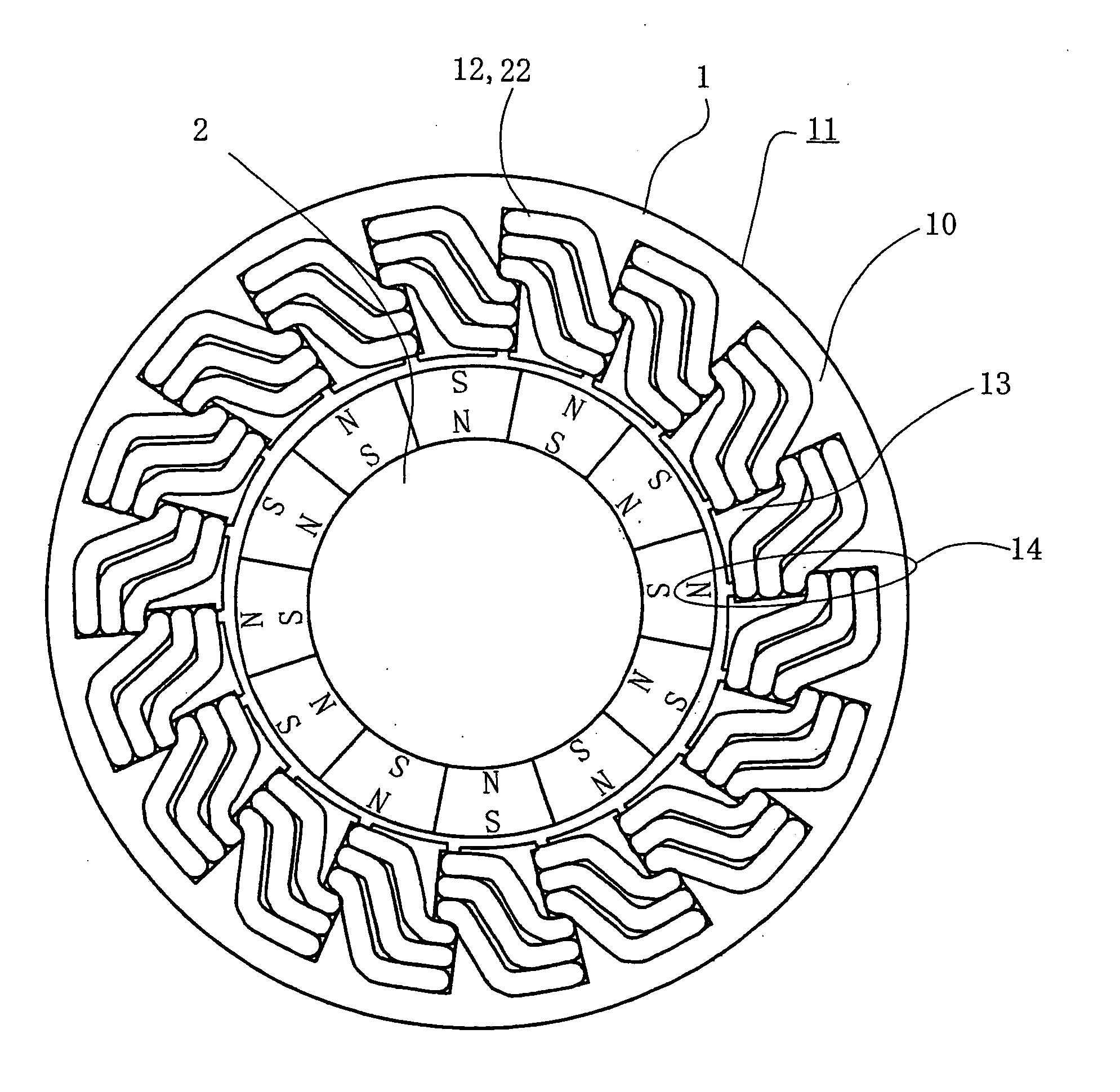
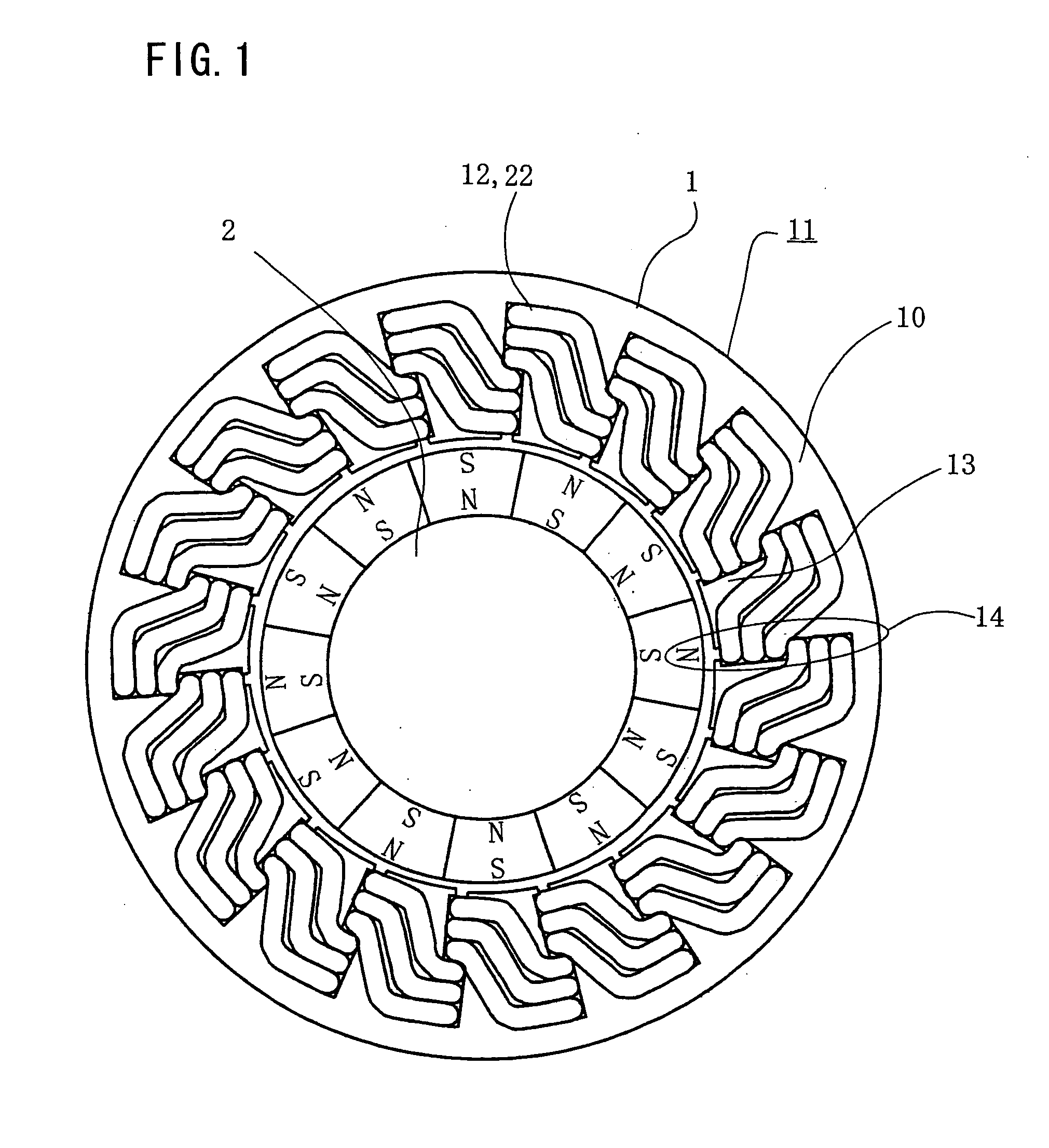
[0027]FIG. 1 is a cross-sectional diagram of a rotating electric machine according to a first embodiment of the invention. FIG. 2A is a perspective diagram showing the shape of each coil unit 12 assembled into a stator 1 of the rotating electric machine of the first embodiment, and FIG. 2B is a cross-sectional diagram showing how a plurality of coil units 12 are fitted.

[0028] Referring to FIG. 1, the rotating electric machine includes the aforementioned stator 1 which serves as an armature (or an assembly including main current-carrying conductors), a rotor 2 which serves as a field-generating assembly, and a bracket (not shown) in which the stator 1 and the rotor 2 are held on a common axis.

[0029] The stator 1 surrounding the rotor 2 includes a stator core 11 and the aforementioned coil units 12. The stator core 11 is built up by laminating a plurality of thin electromagnetic steel sheets to a thickness needed, in which layers of the electromagnetic steel sheets are joined togeth...

second embodiment

[0037]FIGS. 3A and 3B are cross-sectional diagrams of conductors 22 used in a stator 1 of a rotating electric machine according to two varied forms of a second embodiment of the invention. The conductor 22 shown in FIG. 3A has a slightly flat cross section having two flat surfaces, as if produced by flattening a round conductor from two opposite sides, whereas the conductor 22 shown in FIG. 3B has a square cross section having four flat surfaces.

[0038] If the coil unit 12 shown in FIG. 3A or 3B is used for producing individual coil units 12, it is possible to wind and stack successive turns of windings in such a manner that the flat surfaces of adjacent lines of the flat or square conductor 22 are placed face to face with each other. This arrangement serves to decrease a gap between one turn and the next of each conductor 22, making it possible to improve the space factor of windings in individual slots 14.

third embodiment

[0039]FIG. 4 is a fragmentary perspective view of a stator 1 of a rotating electric machine according to a third embodiment of the invention, showing in particular a principal part of the stator 1.

[0040] In this embodiment, individual coil units 12 are fitted in a stator core 11 such that ends 23 of the coil units 12 are taken out of successive slots 14 from one axial end of the stator core 11 in a staggered form. Specifically, one outgoing end 23 of a coil unit 12A is taken out from an innermost layer in one slot 14 and the other outgoing end 23 of the coil unit 12A is taken out from an outermost layer in the adjacent slot 14 as illustrated in FIG. 4. Likewise, one outgoing end 23 of an adjacent coil unit 12B is taken out from an innermost layer in one slot 14 and the other outgoing end 23 of the coil unit 12B is taken out from an outermost layer in the adjacent slot 14.

[0041] Since the ends 23 of the individual coil units 12 serving as connecting parts thereof are concentrated a...


PUM

PropertyMeasurementUnit
thicknessaaaaaaaaaa
electromagneticaaaaaaaaaa
sizeaaaaaaaaaa

Abstract

A plurality of coils concentratedly wound around individual teeth are formed as coil units having a common shape, each of the coil units being made by winding a conductor in a generally rectangular form, stacking one conductor line on top of another, and each of the coil units having two parallel straight portions inserted into the slots on both sides of each tooth. The two parallel straight portions of the conductor of each coil unit are fitted in two adjacent slots in such a way that one straight portion of the conductor is laid in an inner layer in one of the two adjacent slots and the other straight portion of the conductor is laid in an outer layer in the other of the two adjacent slots.

Description

BACKGROUND OF THE INVENTION [0001] 1. Field of the Invention [0002] The present invention relates to a stator of a rotating electric machine, such as an alternating current (AC) generator or an AC motor, in which coils are concentratedly wound on a plurality of teeth of a stator core. [0003] 2. Description of the Background Art [0004] A concentrated-winding type stator of a rotating electric machine includes a stator core which is formed by stacking a plurality of core segments to a specified thickness and joining the core segments by pressure joining or welding and coils concentratedly wound in slots in the stator core. Each of the core segments has multiple teeth extending radially inward from a back yoke and slots formed between the adjacent teeth. These core segments are made by punching an electromagnetic steel sheet by a press, for instance. [0005] Conventionally, a coil is wound around each tooth one layer on top of another by use of a winding machine which pays out a conduct...

Claims


Application Information

Patent Timeline
Patent Type & Authority Applications(United States)
IPC IPC(8): H02K1/00H02K3/00H02K3/04H02K1/16H02K3/18H02K3/52H02K15/02H02K15/085H02K15/095H02K15/14
CPCH02K3/522Y10T29/49009Y10T29/49073H02K15/022
Inventor MAEDA, NAOHIDEASAO, YOSHIHITO
Owner MITSUBISHI ELECTRIC CORP
Why Eureka
Try Eureka