Device and method for inspecting cylindrical member

a cylindrical member and inspection device technology, applied in the direction of belts, instruments, other domestic objects, etc., can solve the problems of insufficient thickness of strip-shaped members, insufficient thickness of overlapped portions, etc., to achieve accurate assessment

Active Publication Date: 2019-10-22
THE YOKOHAMA RUBBER CO LTD
View PDF24 Cites 0 Cited by
  • Summary
  • Abstract
  • Description
  • Claims
  • Application Information

AI Technical Summary

Benefits of technology

[0004]The present technology provides a device and a method for inspecting a cylindrical member capable of accurately assessing a widthwise misalignment of a cylindrical member obtained by molding a strip-shaped member into a cylindrical shape.
[0007]According to the present technology, drum-widthwise end positions of the strip-shaped member wound around the molding drum is detected by the position sensor along the entire length of the strip-shaped member in the longitudinal direction thereof, and the degree of widthwise misalignment of the strip-shaped member wound round the molding drum is calculated by the control unit on the basis of detection data from the position sensor and position data of drum-widthwise end faces that are perpendicular to the drum axial center of the molding drum. Then, the widthwise misalignment of the strip-shaped member is determined to be inside or outside the allowable range on the basis of the calculation result. As a result, the widthwise misalignment of the cylindrical member can be accurately assessed.
[0008]Here, upon molding another strip-shaped member into a cylindrical shape by winding the other strip-shaped member around the outer peripheral surface of the cylindrical member so as to be laminated thereon, drum-widthwise end positions of the other strip-shaped member with respect to the drum-widthwise end faces of the molding drum along the entire length of the other strip-shaped member in the longitudinal direction thereof can be detected by the position sensor, and the degree of widthwise misalignment of the other strip-shaped member can be calculated by the control unit on the basis of the detection data from the position sensor, the detection data from the position sensor for the strip-shaped member wound around the molding drum earlier, and the position data of the drum-widthwise end faces of the molding drum. On the basis of the calculation result, the widthwise misalignment of the other strip-shaped member can also be determined to be inside or outside an allowable range. Accordingly, with respect to the cylindrical member formed on the molding drum, the widthwise misalignment of the other strip-shaped member, which is subsequently laminated, can be accurately assessed with respect to the strip-shaped member that was wound around the molding drum earlier. Specifically, the degree of widthwise misalignment of the cylindrical member formed by laminating a plurality of the strip-shaped members on top of each other can be accurately assessed.
[0010]The thickness of the strip-shaped member, which has been molded into the cylindrical shape on the molding drum, can be detected by a thickness sensor in a peripheral area over which the longitudinal distal end and the longitudinal rear end of the strip-shaped member face each other, and whether the spliced state of the strip-shaped member is appropriate can be determined on the basis of the detection data from the thickness sensor. Specifically, when the longitudinal distal end and the longitudinal rear end overlap with each other, the thickness of the strip-shaped member, i.e., the thickness of the overlapped portion, in the peripheral area is excessive in comparison to the original thickness of the strip-shaped member. On the other hand, when the longitudinal distal end and the longitudinal rear end are separated from each other and are not placed against each other, the thickness of the strip-shaped member in the peripheral area is substantially zero. Thus, the appropriateness of the spliced state of the strip-shaped member can be accurately assessed on the basis of the detection data from the thickness sensor.

Problems solved by technology

Manufacturing tires using the cylindrical member subject to this kind of strain makes it difficult to ensure consistent tire quality.
Specifically, when the longitudinal distal end and the longitudinal rear end overlap with each other, the thickness of the strip-shaped member, i.e., the thickness of the overlapped portion, in the peripheral area is excessive in comparison to the original thickness of the strip-shaped member.

Method used


Image

  • Device and method for inspecting cylindrical member
  • Device and method for inspecting cylindrical member
  • Device and method for inspecting cylindrical member

Examples


Embodiment Construction

[0019]A device and a method for inspecting a cylindrical member of the present technology will be described below on the basis of an embodiment illustrated in the drawings.

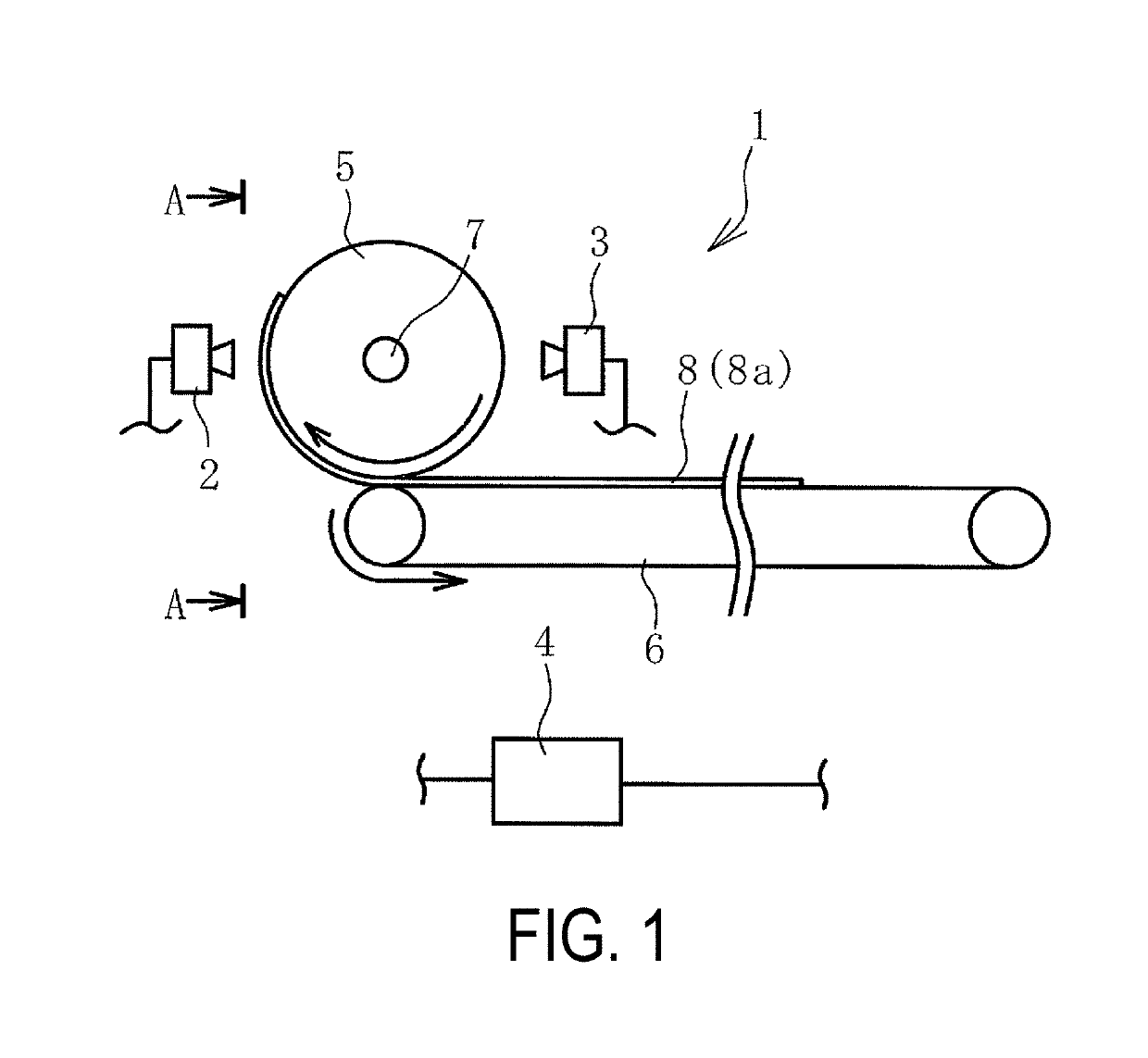
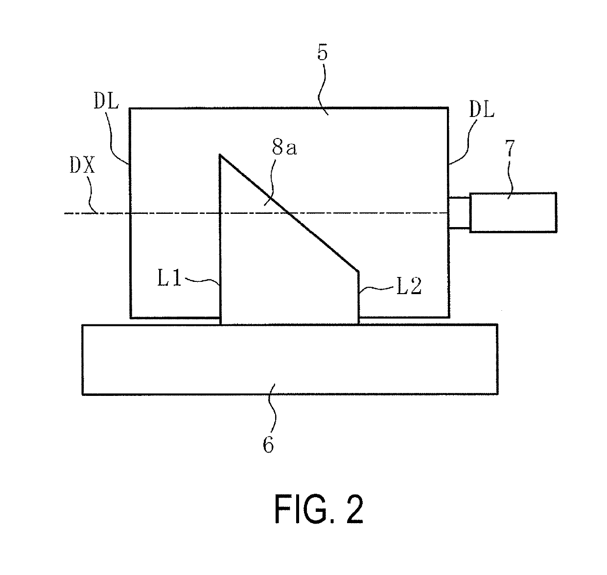
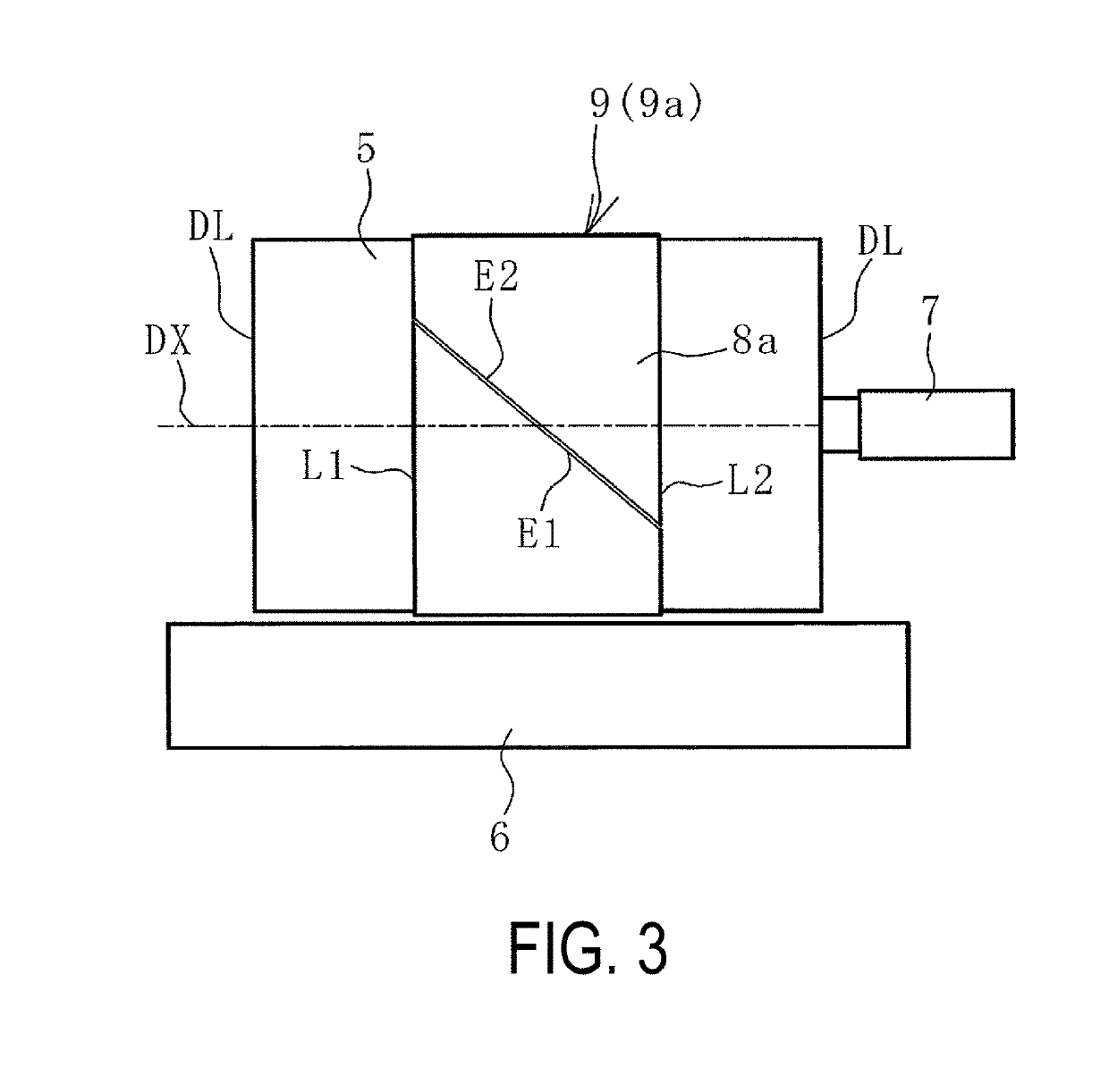
[0020]An inspection device 1 for a cylindrical member of the present technology illustrated in FIGS. 1 and 2 (hereinafter referred to as an inspection device 1) inspects a widthwise misalignment of a cylindrical member 9 (9a, 9b) molded by winding a strip-shaped member 8 (8a, 8b) around an outer peripheral surface of a molding drum 5. The strip-shaped member 8 is molded into a cylindrical shape by placing a longitudinal distal end (a distal end edge) and a longitudinal rear end (a rear end edge) thereof against each other.

[0021]Examples of the strip-shaped member 8 include a belt member used as a reinforcing member for rubber products such as tires, and various extruded rubber members such as a tread rubber and a side rubber for pneumatic tires. The belt member is a member in which a plurality of steel cords dispo...


PUM

PropertyMeasurementUnit
cylindrical shapeaaaaaaaaaa
lengthaaaaaaaaaa
circumferenceaaaaaaaaaa

Abstract

Provided are a device and a method for inspecting a cylindrical member. During inspection of a cylindrical member, a degree of widthwise misalignment of a strip-shaped member wound around a molding drum is calculated by a control unit on the basis of detection data from a position sensor and position data of drum-widthwise end faces that are perpendicular to a drum axial center of the molding drum, and the widthwise misalignment of the strip-shaped member is determined to be inside or outside an allowable range on the basis of the calculation result.

Description

TECHNICAL FIELD[0001]The present technology relates to a device and a method for inspecting a cylindrical member, and more specifically, to a device and method for inspecting a cylindrical member capable of accurately assessing a widthwise misalignment of a cylindrical member obtained by molding a strip-shaped member into a cylindrical shape.BACKGROUND ART[0002]In the manufacturing steps of rubber products such as tires, a strip-shaped belt member is used that is made of a plurality of steel cords disposed side by side at a predetermined cord angle and covered with rubber. This belt member is formed by cutting the member obtained by covering the steel cords disposed side by side with rubber, at a predetermined length and at a predetermined angle set in accordance with the cord angle, and bonding together a plurality of the cut members (See Japanese Unexamined Patent Application Publication No. 2009-226817A, for example). This strip-shaped belt member is wound around a molding drum a...

Claims


Application Information

Patent Timeline
Patent Type & Authority Patents(United States)
IPC IPC(8): G01B21/08B29D30/30B29D29/00B29D30/00B29C65/00B29D30/16B29K21/00
CPCB29D29/00B29C65/00B29D30/0061G01B21/08B29D30/3007B29D30/00B29D30/1621B29K2021/00
Inventor MATSUMURA, KENSUKE
Owner THE YOKOHAMA RUBBER CO LTD
Why Eureka
Try Eureka