
Impact point estimation apparatus

a technology of impact point and estimation apparatus, which is applied in the direction of sports apparatus, instruments, gymnastics exercise, etc., can solve the problems of difficult sensor attachment and significant influence of golf swing, and achieve the effect of impact point of the ball in a simple and highly accurate manner

Active Publication Date: 2019-10-29
SUMITOMO RUBBER IND LTD
View PDF14 Cites 2 Cited by
  • Summary
  • Abstract
  • Description
  • Claims
  • Application Information

AI Technical Summary

Benefits of technology

[0005]An object of the present invention is to provide an impact point estimation apparatus, method and program that enable the point at which the ball impacts the face surface when a golf club is swung to be estimated in a simple and highly accurate manner.
[0028]According to the present invention, the impact point is estimated from the output value of at least one of an angular velocity sensor and an acceleration sensor that is attached to at least one of the grip and the shaft. Accordingly, the impact point of the ball on the face surface can be estimated in a simple manner. Also, the sensor data that is targeted for analysis is time series sensor data acquired in an analysis period. The analysis period includes an initial period after impact, and is a period before a predetermined short time period (typically, 0.01 s) has elapsed from impact. The above analysis period is a period in which the initial few waves (from the first wave to around the third wave at most) of the stress wave that occurs due to impact and propagates from the face surface through the shaft to the sensor appear. Normally, a large number of the waves start to interfere after this initial analysis period, and it can become difficult to analyze the characteristics of the stress wave. However, here, the above analysis period is targeted for analysis, thus facilitating the analysis of the characteristics of the stress wave, and consequently enabling the impact point of the ball to be estimated in a simple and highly accurate manner.

Problems solved by technology

However, with the method of Patent Literature 1, the sensors are attached to the back side of the face surface, and thus attaching the sensors may be difficult.
Also, the presence of the sensors can significantly affect the golf swing.

Method used


Image

  • Impact point estimation apparatus
  • Impact point estimation apparatus
  • Impact point estimation apparatus

Examples


Embodiment Construction

[0040]Hereinafter, an impact point estimation apparatus, method and program that estimate the impact point at the time of a golf swing according to one embodiment of the present invention will be described, with reference to the drawings.

1. Overall Analysis System Configuration

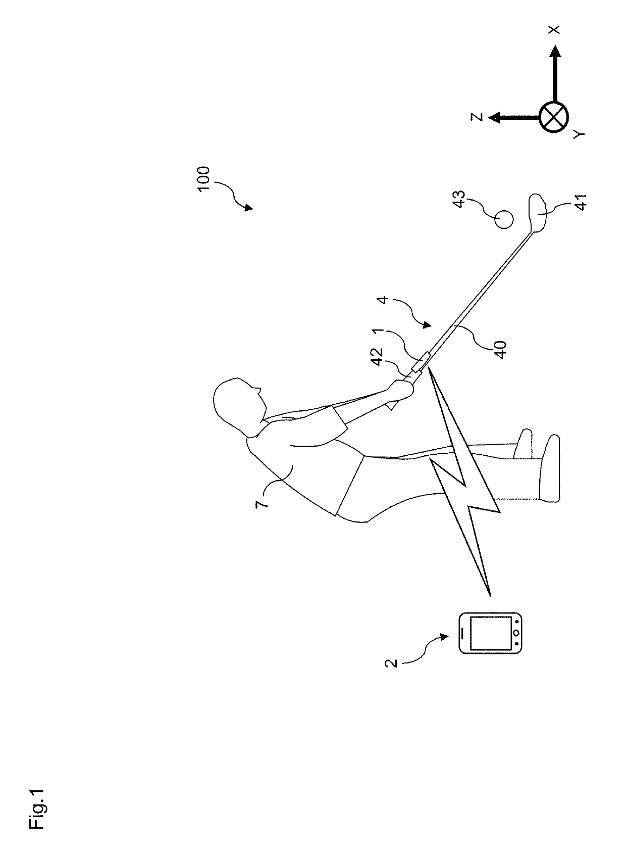
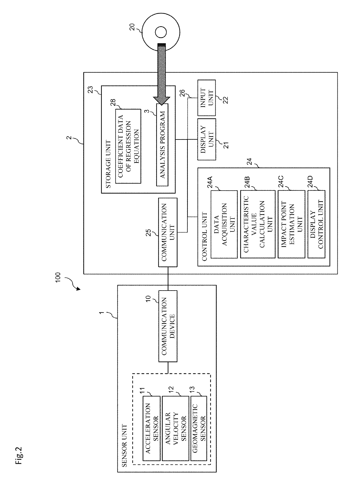
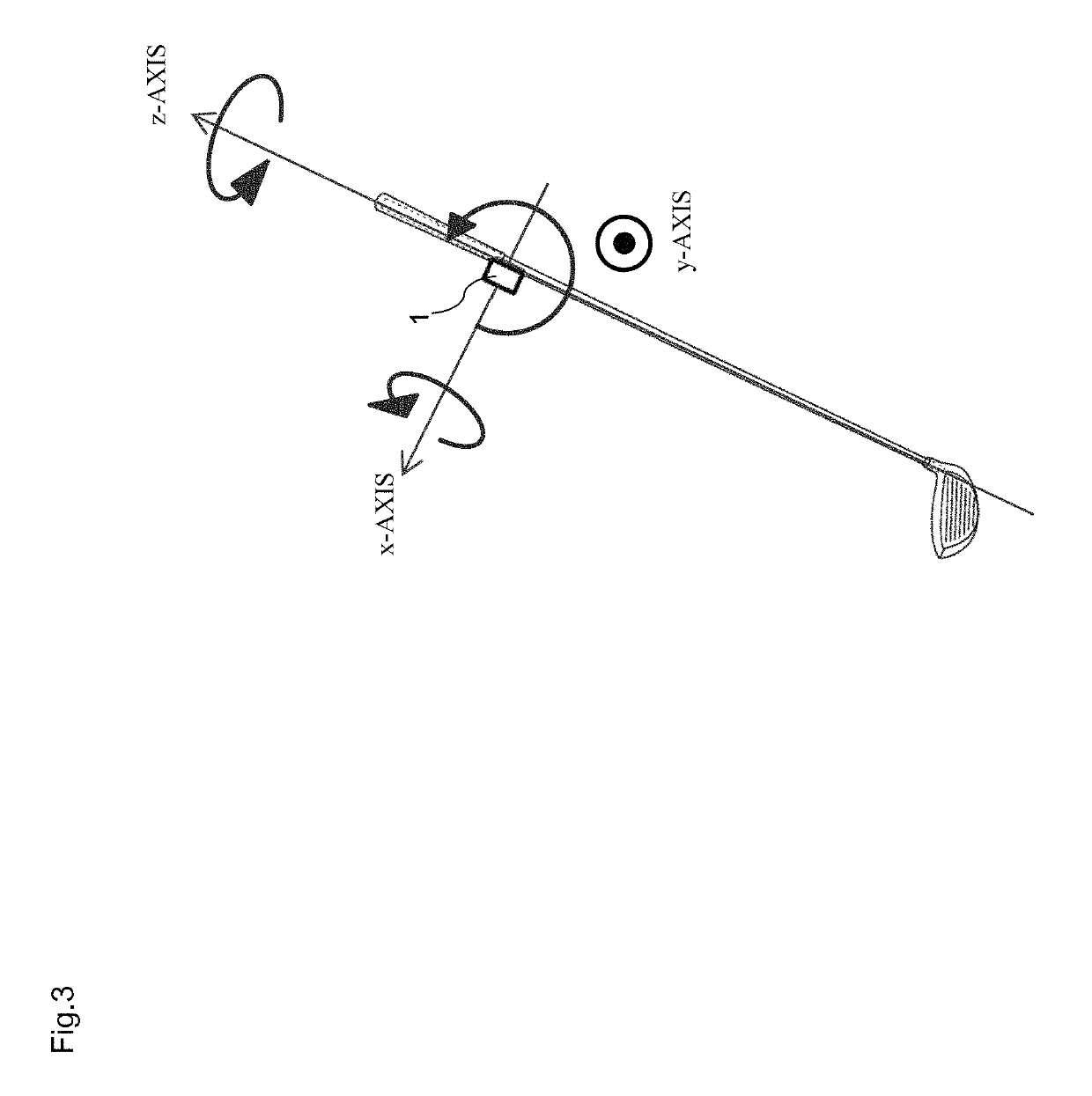
[0041]The overall configuration of a swing analysis system 100 that is provided with an analysis apparatus 2, which is an impact point estimation apparatus according to the present embodiment, is shown in FIGS. 1 and 2. The analysis apparatus 2 is an apparatus that analyzes a golf swing. More specifically, the analysis apparatus 2 has a function of estimating the impact point (impact position) of a golf ball 43 on a face surface 41a (see FIG. 6) of a head 41 when a golfer 7 swings a golf club 4 and hits the golf ball 43. Information on the impact point estimated by the analysis apparatus 2 can be used to, for example, grasp how often the golfer 7 is hitting the ball 43 in the sweet area during golf practice. A...


PUM


Abstract

Provided is an impact point estimation apparatus for estimating an impact point on a face surface of a head when a golf club having a grip, a shaft and the head is swung and hits a golf ball. The apparatus has an acquisition unit, a calculation unit, and an estimation unit. The acquisition unit is configured to acquire time series sensor data that is output from at least one of an angular velocity sensor and an acceleration sensor that is attached to at least one of the grip and the shaft. The calculation unit is configured to calculate a characteristic value of an initial stress wave that occurs due to impact from the sensor data acquired in an analysis period including an initial period after impact. The estimation unit is configured to estimate the impact point on the face surface, according to the characteristic value. The analysis period is before a predetermined short time period has elapsed from impact.

Description

CROSS REFERENCE TO RELATED APPLICATIONS[0001]This application claims a priority to Japanese Patent Application No. 2015-197897 filed on Oct. 5, 2015, which is hereby incorporated by reference in its entirety.FIELD OF INVENTION[0002]The present invention relates to an impact point estimation apparatus, method and program that estimate the point at which a golf ball impacts the face surface of the head of a golf club when the golf club is swung and hits the golf ball.BACKGROUND[0003]Heretofore, technologies that estimate the point at which the golf ball impacts the face surface when a golf club is swung have been proposed. For example, WO 2009 / 069698 (hereinafter called “Patent Literature 1”) discloses an apparatus that estimates the impact point from the output signals of a plurality of sensors for detecting vibration at the time of ball strike that are attached to the back of the face surface.SUMMARY OF INVENTION[0004]However, with the method of Patent Literature 1, the sensors are ...

Claims


Application Information

Patent Timeline
Patent Type & Authority Patents(United States)
IPC IPC(8): A63F9/24A63B24/00A63B69/36G06F17/00A63F13/00G01P1/00G06K9/00
CPCG06K9/00342A63B24/0003A63B69/36G01P1/06A63B2220/53A63B2220/833A63B2208/0204A63B2220/40A63B2220/34G06V40/23G06F2218/08
Inventor ONUKI, MASAHIDE
Owner SUMITOMO RUBBER IND LTD
Learn More