Supercharge Your Innovation With Domain-Expert AI Agents!

Stranded conductor and method for manufacturing stranded conductor

a technology of stranded conductors and manufacturing methods, applied in the field of stranded conductors, can solve problems such as filament unevenness

Active Publication Date: 2019-10-29
FURUKAWA ELECTRIC CO LTD +1
View PDF28 Cites 1 Cited by
  • Summary
  • Abstract
  • Description
  • Claims
  • Application Information

AI Technical Summary

Benefits of technology

The present invention provides a way to make stranded conductors that have fewer defects, such as uneven filament thickness and flattened parts. The method of manufacturing helps to prevent these defects from occurring.

Problems solved by technology

Specifically, for example, in the case that the lay length is short, the angle of the filaments to be stranded together, with respect to the central axis of the stranded conductor, is large, and as a result, strand unevenness may occur in the filaments.

Method used


Image

  • Stranded conductor and method for manufacturing stranded conductor
  • Stranded conductor and method for manufacturing stranded conductor
  • Stranded conductor and method for manufacturing stranded conductor

Examples


first embodiment

[0072]A first embodiment of this invention will be described with reference to FIGS. 1 to 6.

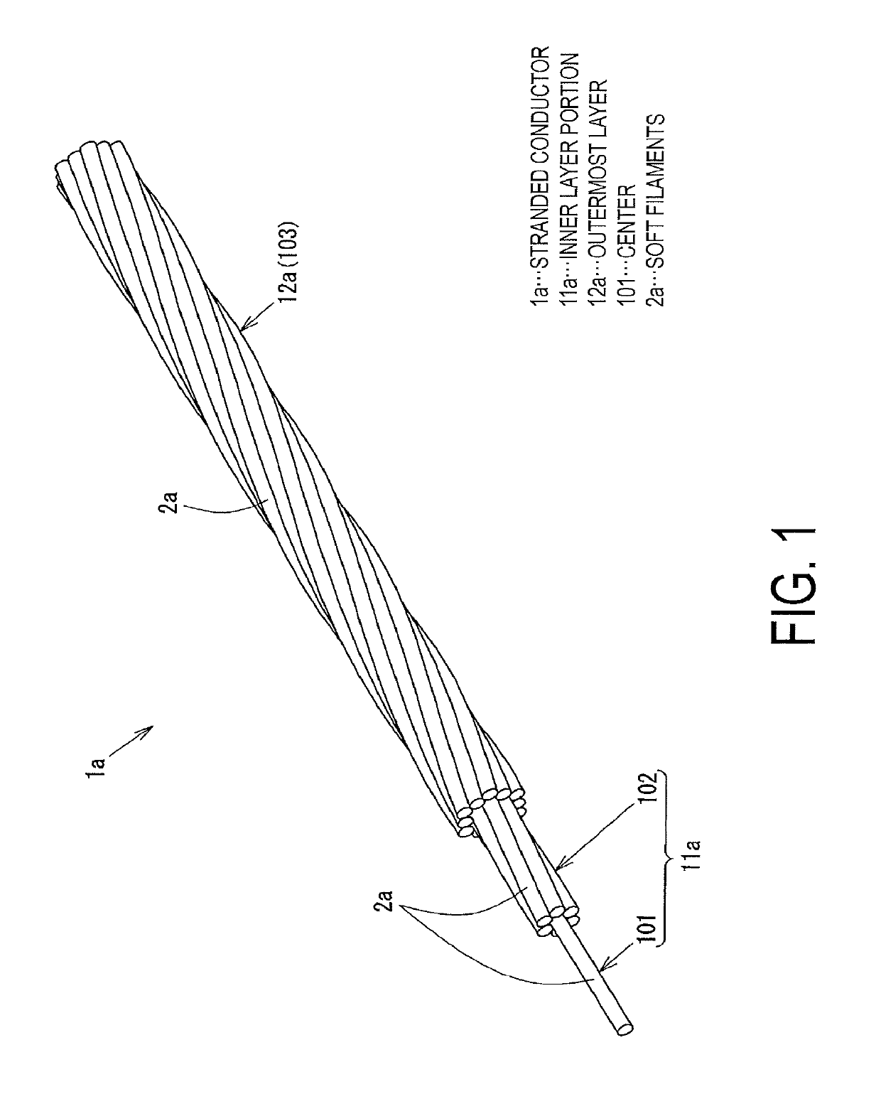
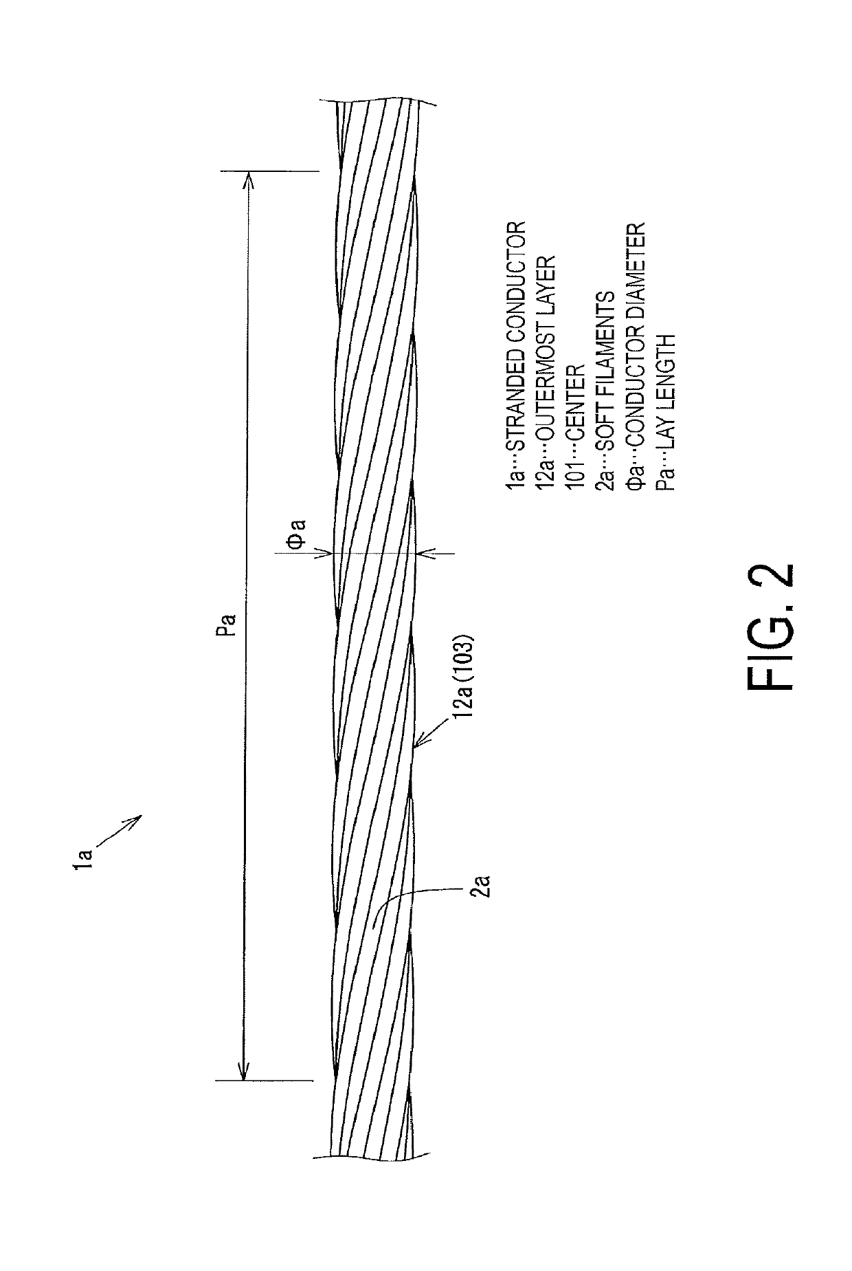
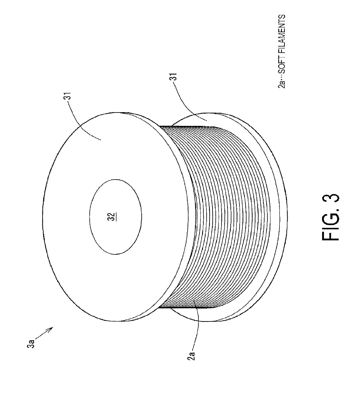
[0073]FIG. 1 is a perspective view of a stranded conductor 1a, according to the first embodiment. FIG. 2 is a front view of the stranded conductor 1a according to the first embodiment. FIG. 3 is a perspective view of a bobbin 3a, with a soft filament 2a wound thereon. FIG. 4 is a schematic diagram of a stranding machine 4a, according to the first embodiment. FIG. 5 is an enlarged perspective view of a second layer stranding unit 5, according to the first embodiment. FIG. 6 is a flowchart illustrating a method for manufacturing the stranded conductor 1a according to the first embodiment.

[0074]FIG. 1 is a perspective view of the stranded conductor 1a. To ensure that the 3-layer structure of the stranded conductor 1a can be easily understood, the lengths of the soft filaments 2a are illustrated, at one end of the stranded conductor 1a, in such a manner that the length decreases gradually, from a...

second embodiment

[0203]A second embodiment of this invention will be described with reference to FIGS. 8 to 11. Of the elements to be described below, elements similar to those of the above-described first embodiment are assigned the same reference characters and descriptions thereof are omitted.

[0204]FIG. 8 is a perspective view of a stranded conductor 1c, according to the second embodiment. FIG. 9 is a front view of the stranded conductor 1c according to the second embodiment. FIG. 10 is a schematic diagram of a stranding machine 4b, according to the second embodiment. FIG. 11 is a flowchart illustrating a method for manufacturing the stranded conductor 1c according to the second embodiment.

[0205]FIG. 8 is a perspective view of the stranded conductor 1c. To ensure that the 4-layer structure of the stranded conductor 1c can be easily understood, the lengths of the soft filaments 2a are illustrated, at one end of the stranded conductor 1c, in such a manner that the length decreases gradually, from t...


PUM

PropertyMeasurementUnit
tensionaaaaaaaaaa
tensionaaaaaaaaaa
tensionaaaaaaaaaa

Abstract

According to embodiments of the present invention, a stranded conductor is formed in which the occurrence of defects, such as strand unevenness of filaments and outward protrusion of filaments, is inhibited. According to embodiments of the present invention, a stranded conductor (1a) includes soft filaments (2a) stranded together. The soft filaments (2a) include a soft filament made of an aluminum material, disposed along a center (101), and include six soft filaments, twelve soft filaments, and eighteen soft filaments made of an aluminum material, disposed around and concentrically with the center. The filaments are softened filaments that are softened. A lay length (Pa) is from 6.2 times to 15.7 times a conductor diameter of the stranded conductor.

Description

TECHNICAL FIELD[0001]This invention relates to a stranded conductor formed of aluminum filaments stranded together and a method for manufacturing the stranded conductor.BACKGROUND ART[0002]Vehicles, such as automobiles, include a wire harness installed therein for connecting electronic devices together to send and receive signals and supply power, for example. The wire harness is formed of insulated electrical wires, which are conductors each covered with an insulating covering, and connectors that can be connected to, for example, electronic devices.[0003]An example of an insulated electrical wire, which is a constituent of such a wire harness, is disclosed in Patent document 1, for example. In Patent Document 1, the insulated electrical wire is formed of a core wire (hereinafter referred to as a stranded conductor), an insulating covering, and a lubricant. The stranded conductor is formed by a radial multi-layer structure including nineteen aluminum filaments stranded together, th...

Claims


Application Information

Patent Timeline
Patent Type & Authority Patents(United States)
IPC IPC(8): H01B5/08H01B1/02D07B1/14D07B1/08D07B1/06H01B13/02D07B3/02
CPCD07B1/0693D07B1/08H01B13/02H01B13/0221H01B5/08H01B1/023D07B1/06D07B1/147D07B2801/14D07B2201/2059D07B2205/306D07B2201/2031D07B2501/406H01B13/0285D07B3/02D07B2801/12D07B2207/4045D07B2201/204D07B2201/2025
Inventor YOSHIMARU, MASAHIROOSUGA, HIDEYUKI
Owner FURUKAWA ELECTRIC CO LTD
Features
  • R&D
  • Intellectual Property
  • Life Sciences
  • Materials
  • Tech Scout
  • Unparalleled Data Quality
  • Higher Quality Content
  • 60% Fewer Hallucinations
Learn More