Check patentability & draft patents in minutes with Patsnap Eureka AI!

De-icing system for a wind turbine blade

a technology of wind turbine blades and de-icing systems, which is applied in the direction of efficient propulsion technologies, mechanical equipment, machines/engines, etc., can solve the problems of reducing turbine efficiency and/or operational noise levels, ice which breaks away from the blade surface can present a falling hazard, and the de-icing operation of the blade de-icing system can be improved, and the heat loss of heated fluid can be minimized.

Active Publication Date: 2019-10-29
LM WP PATENT HLDG
View PDF12 Cites 6 Cited by
  • Summary
  • Abstract
  • Description
  • Claims
  • Application Information

AI Technical Summary

Benefits of technology

[0012]In this system, the outboard portion of the blade is heated from the tip end back along the length of the outboard portion, and then returned via an insulated channel to reduce heat loss in system, and provide for a more efficient de-icing system. By insulating the outflow channel of the de-icing system from the root end to the tip end of the blade, accordingly the working fluid, preferably heated air, is maintained at a high temperature until it reaches the heating channel at the tip end of the blade. As a result, the working fluid starts to heats the leading edge of the blade from a location at or near the tip end of the blade, with the fluid at the highest temperature for the outermost sections of the blade, where the de-icing operation has the greatest impact on the blade and turbine performance. As a result, the de-icing of the outermost areas of the blade is not affected by any heat loss due to heating of the relatively more inboard sections of the blade.
[0074]If the outflow channel and the heating channel are connected at the tip end, then the heated fluid is conveyed to the heating channel at the tip end. The use of a flow diverting baffle to divert a portion of this flow to a location spaced from the tip end allows for some of the heated fluid to be redirected to a secondary location, such that the heated fluid reaches the leading edge of the blade at said secondary location without significant heat losses. Accordingly, the de-icing operation of the blade de-icing system can be improved, as heat losses of the heated fluid can be minimized prior to the heating of the blade leading edge.

Problems solved by technology

When wind turbines are operated in cold-weather climates, the potential build-up of ice on the wind turbine blades presents challenges for turbine performance.
In a first aspect, any ice formation on the blade surfaces will disrupt the blade aerodynamics, which may lead to a reduction in turbine efficiency and / or increased operational noise levels.
In a further aspect, ice which breaks away from blade surfaces can present a falling hazard.
However, such prior art hot air systems are often inefficient, and can require large amounts of energy to ensure that ice is prevented from forming at the tip end of the wind turbine blades, where the impact of any ice formation on the blade aerodynamics is most significant.
Furthermore, the use of such hot air systems can introduce additional complications in terms of increased blade weight and / or structural strain, which can affect the practicability of such solutions.

Method used


Image

  • De-icing system for a wind turbine blade
  • De-icing system for a wind turbine blade
  • De-icing system for a wind turbine blade

Examples


Embodiment Construction

[0080]Embodiments of the invention will now be described, by way of example only, with reference to the accompanying drawings, in which:

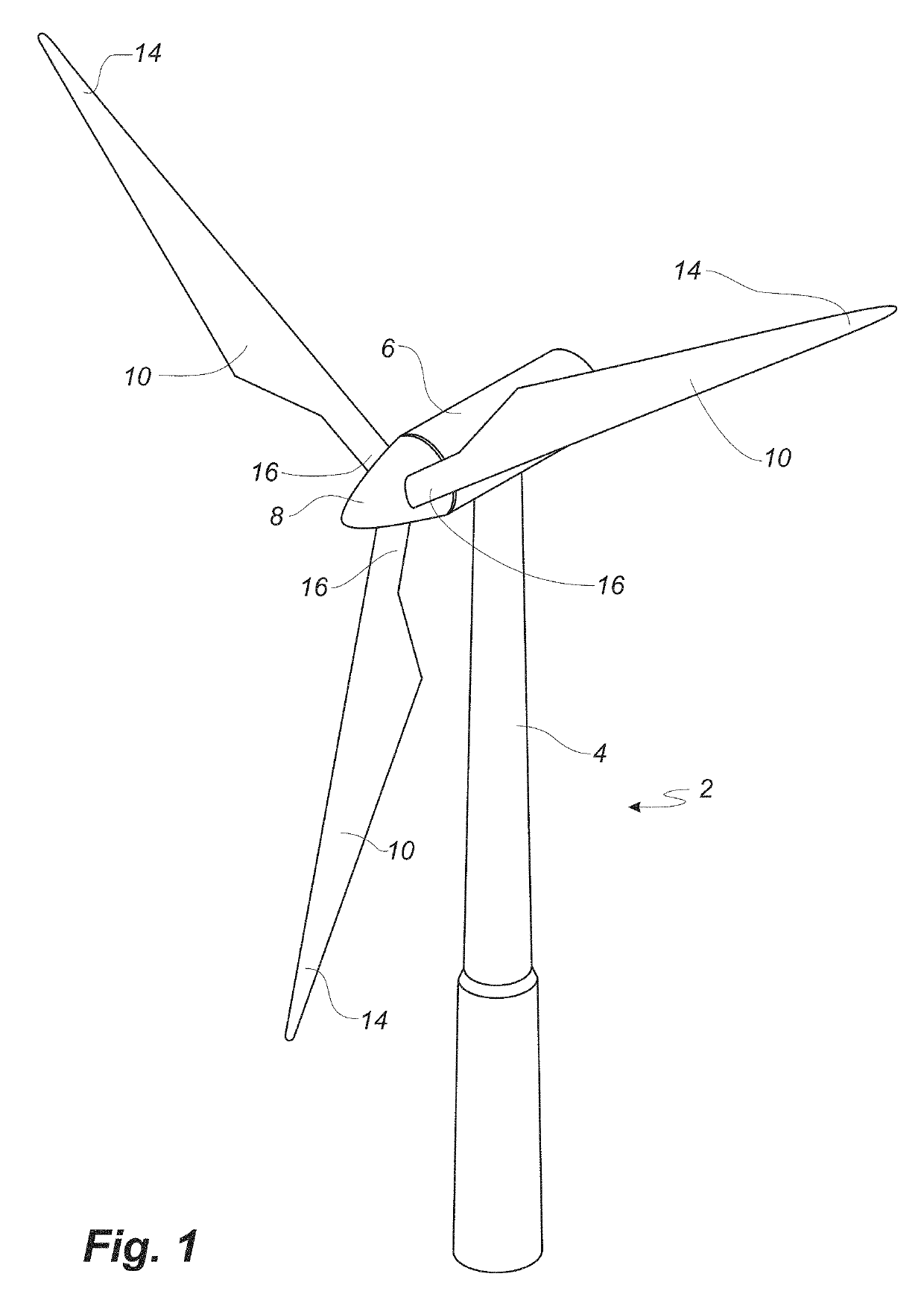
[0081]FIG. 1 shows a wind turbine;

[0082]FIG. 2 shows a schematic view of a wind turbine blade according to the invention;

[0083]FIG. 3 shows a schematic view of an airfoil profile of the blade of FIG. 2;

[0084]FIG. 4 shows a schematic view of the wind turbine blade of FIG. 2, seen from above and from the side;

[0085]FIG. 5 illustrates a cross-sectional plan view of a known wind turbine blade structure;

[0086]FIG. 6 illustrates a cross-sectional plan view of a wind turbine blade having a de-icing system according to an embodiment of the invention;

[0087]FIG. 7 illustrates a cross-sectional plan view of a wind turbine blade having a de-icing system according to a further embodiment of the invention;

[0088]FIG. 8 illustrates a cross-sectional plan view of a wind turbine blade having a de-icing system according to a further embodiment of the invention;

[0089]F...


PUM


Abstract

A wind turbine blade is described having a de-icing system which is arranged to heat at least a portion of the leading edge of the wind turbine blade, to prevent the formation of ice on the blade, or to remove any existing surface ice. The de-icing system comprises insulated flow channels which are arranged to circulate a heated fluid from a heating element to the tip end of the blade, and to de-ice the blade leading edge starting from the tip end towards the root end of the blade. The de-icing system is arranged to operate in the outboard portion of the blade, where the de-icing effect provides the most benefits to turbine operation. Further features of the de-icing system include an improved mounting arrangement of the de-icing system, an improved tip end configuration of the de-icing system, and providing portions of the de-icing system as double-walled inflatable insulating tubes.

Description

[0001]This is a National Phase Application filed under 35 U.S.C. 371 as a national stage of PCT / EP2015 / 070035, filed Sep. 2, 2015, an application claiming the benefit of European Application No. 14183144.6, filed Sep. 2, 2014, the content of each of which is hereby incorporated by reference in its entirety.FIELD OF THE INVENTION[0002]The present invention relates to a de-icing system for a wind turbine blade.BACKGROUND OF THE INVENTION[0003]When wind turbines are operated in cold-weather climates, the potential build-up of ice on the wind turbine blades presents challenges for turbine performance. In a first aspect, any ice formation on the blade surfaces will disrupt the blade aerodynamics, which may lead to a reduction in turbine efficiency and / or increased operational noise levels. In a further aspect, ice which breaks away from blade surfaces can present a falling hazard. In this regard, wind turbine blades in such locations are often provided with systems to deliver ice prevent...

Claims


Application Information

Patent Timeline
Patent Type & Authority Patents(United States)
IPC IPC(8): F03D80/40F03D1/06
CPCF03D80/40F05B2250/291F05B2260/202F05B2270/303F03D1/0608F03D1/0633F03D1/065F05B2240/301Y02E10/721F03D1/0675F05B2260/20Y02E10/72Y02T50/60
Inventor PHILIPSEN, MORTENKORSGAARD, JOHNKILLICK, DAVID
Owner LM WP PATENT HLDG
Features
  • R&D
  • Intellectual Property
  • Life Sciences
  • Materials
  • Tech Scout
  • Unparalleled Data Quality
  • Higher Quality Content
  • 60% Fewer Hallucinations
Learn More