Surface roughening of powder metal parts

a technology of surface roughening and powder metal parts, which is applied in the direction of mechanical actuators, mechanical equipment, hoisting equipment, etc., can solve the problems of difficult or impossible to achieve using conventional methods, and achieve the effects of reducing the difficulty of conventional methods

Active Publication Date: 2019-10-29
KEYSTONE POWDERED METAL
View PDF3 Cites 2 Cited by
  • Summary
  • Abstract
  • Description
  • Claims
  • Application Information

AI Technical Summary

Benefits of technology

[0005]This invention relates to a method for applying a rough surface to a powder metal part. The level of surface roughness can be controlled to provide the powder metal part with one or more surfaces having desired levels of surface roughness. This technique can be used to impart surface roughness to surfaces of parts which would be difficult or impossible to attain using conventional methods. For instance, the method of this invention can be used to impart surface roughness to surfaces which are non-uniform, curved, rounded, tapered, or which have multiple surface geometries. It can also be used to impart surface roughness to areas on a part which are obstructed, partially obstructed, recessed, or otherwise not readily accessible. The technique of this invention also provides a superior and relatively uniform roughness over the surface of the part which has surface characteristics which are indicative of electrical discharge machining.

Problems solved by technology

This technique can be used to impart surface roughness to surfaces of parts which would be difficult or impossible to attain using conventional methods.

Method used


Image

  • Surface roughening of powder metal parts
  • Surface roughening of powder metal parts

Examples


example 1

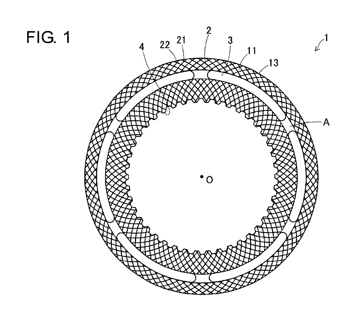
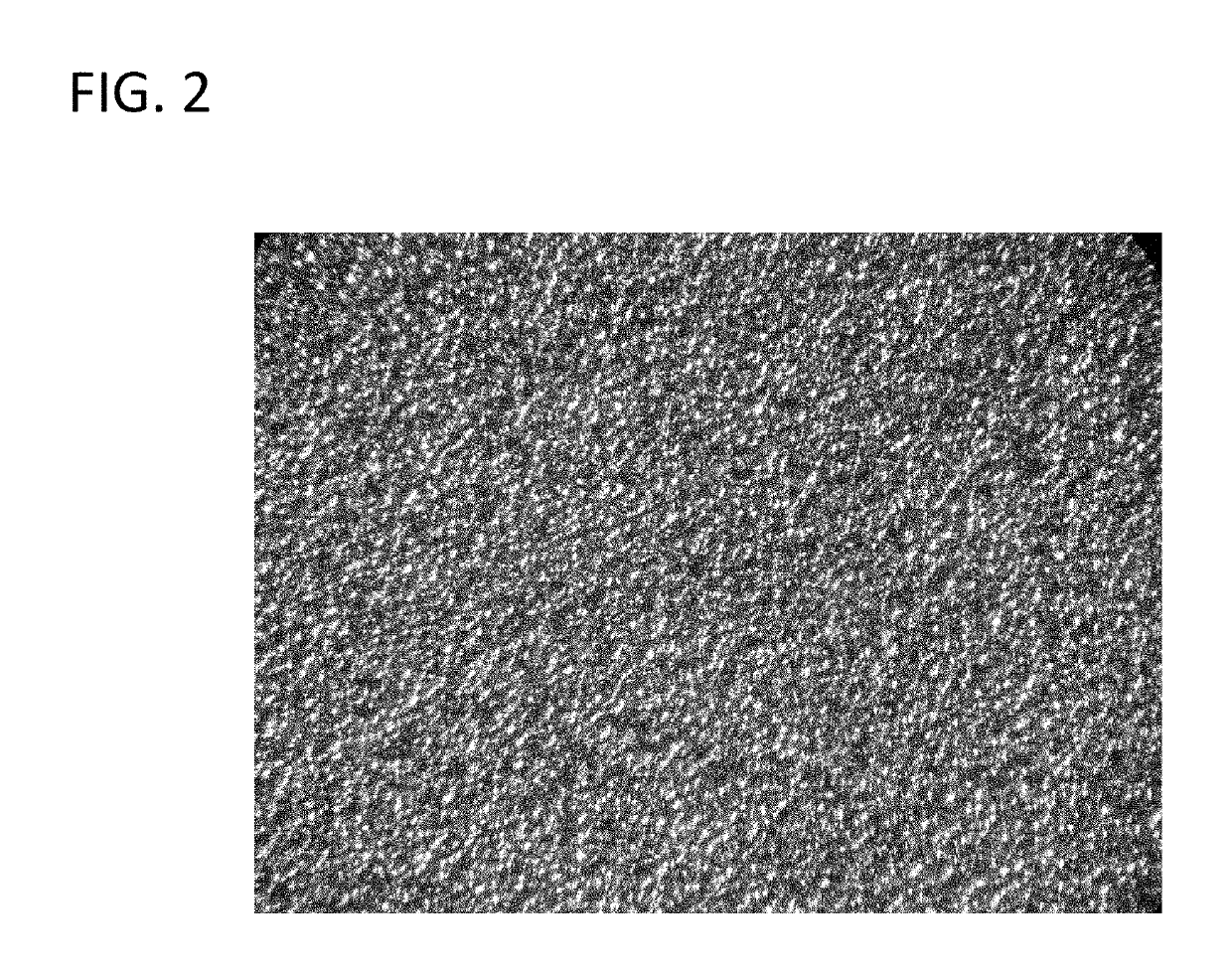
[0035]A clutch plate of the design illustrated in FIG. 1 can be manufacture in accordance with this invention. Such a clutch plate is further described in U.S. Pat. No. 9,188,168. The teachings of U.S. Pat. No. 9,188,168 are incorporated by reference herein for the purpose of describing such a clutch plate. In any case, such a clutch plate 1 will be comprised of a friction engagement surface 13, a plurality of windows 3, and a spline 4. The clutch plate will also typically include lubricating grooves 2, grooves 21, intersection points 22 and empty portions A as illustrated in FIG. 1. The friction engagement surface of the clutch plate will have a surface roughness having an Ra which is within the range of 10 to 100 microinches, as measured with a profilometer having a chisel tip, and will have a friction engagement surface having surface characteristics which are indicative of electrical discharge machining as shown in the FIG. 2. As can be seen in FIG. 2 the friction engagement sur...


PUM

PropertyMeasurementUnit
temperatureaaaaaaaaaa
surface areaaaaaaaaaaa
temperatureaaaaaaaaaa

Abstract

It has been found that metal parts having rough surfaces can be manufactured by (1) compacting a metal powder under high pressure in a mold to make a green part, wherein at least one face of the mold is roughened by electrical discharge machining to have an Ra of 10 to 200 micro-inches, as measured with a profilometer having a stylus tip, (2) heating the green metal part to a temperature of at least 1500° F. to sinter the green metal part to produce the metal part having at least one rough surface, wherein the rough surface has an Ra which is within the range of 10 to 200 micro-inches, as measured with a profilometer having a chisel tip, and (3) optionally, buffing, classifying, deburring and/or washing the metal part. This method can be beneficially used in manufacturing clutch plates, pressure plates, and cam shaft sprockets.

Description

[0001]This application claims the benefit of U.S. Provisional Patent Application Ser. No. 62 / 305,740 filed on Mar. 9, 2016. The teachings of U.S. Provisional Patent Application Ser. No. 62 / 305,740 are incorporated by reference herein in their entirety.BACKGROUND OF THE INVENTION[0002]It is desirable for metal parts that are used in a wide variety of applications to have one or more surfaces which have a rough surface texture. For instance, it is desirable for clutch plates, pressure plates, camshaft sprockets, crankshaft sprockets, and a wide variety of other parts to include surfaces which are relatively rough. For instance, parts having at least one rough surface are frequently used in applications where the part is adapted for providing non-rotating engagement with another part in an article of manufacture. In such cases, it is also typically desirable for the rough surface of the part to be surface hardened to provide for better engagement with another part having a softer engag...

Claims


Application Information

Patent Timeline
Patent Type & Authority Patents(United States)
IPC IPC(8): B22F5/00F16H55/30F16H55/06F16D13/70F16D13/64B22F3/24B22F3/16F16D13/74B22F3/03
CPCB22F3/16F16D13/64F16H55/06F16D13/74F16H55/30B22F3/24F16D13/70B22F5/00B22F3/03B22F2003/247B22F3/164B22F5/106B22F2003/166B22F2003/245B22F2998/10B22F2999/00F16D13/648F16D2200/0008F16D2200/0086F16D2250/0038B22F3/02B22F3/10B22F2003/248B22F2201/30
Inventor HERBSTRITT, MATTHEW G.ANDERSON, GARY L.
Owner KEYSTONE POWDERED METAL
Why Eureka
Try Eureka