Froth flotation with anisotropic particle collectors

a technology of anisotropic particle collector and froth flotation, which is applied in the direction of flotation, solid separation, etc., can solve the problem that the selection of collectors can significantly affect the efficiency of the froth flotation process

Active Publication Date: 2019-11-05
INT BUSINESS MASCH CORP
View PDF8 Cites 1 Cited by
  • Summary
  • Abstract
  • Description
  • Claims
  • Application Information

AI Technical Summary

Problems solved by technology

The efficacy of the separation achieved by the froth flotation process can therefore be significantly impacted by the selection of the collector.

Method used


Image

  • Froth flotation with anisotropic particle collectors
  • Froth flotation with anisotropic particle collectors
  • Froth flotation with anisotropic particle collectors

Examples


Embodiment Construction

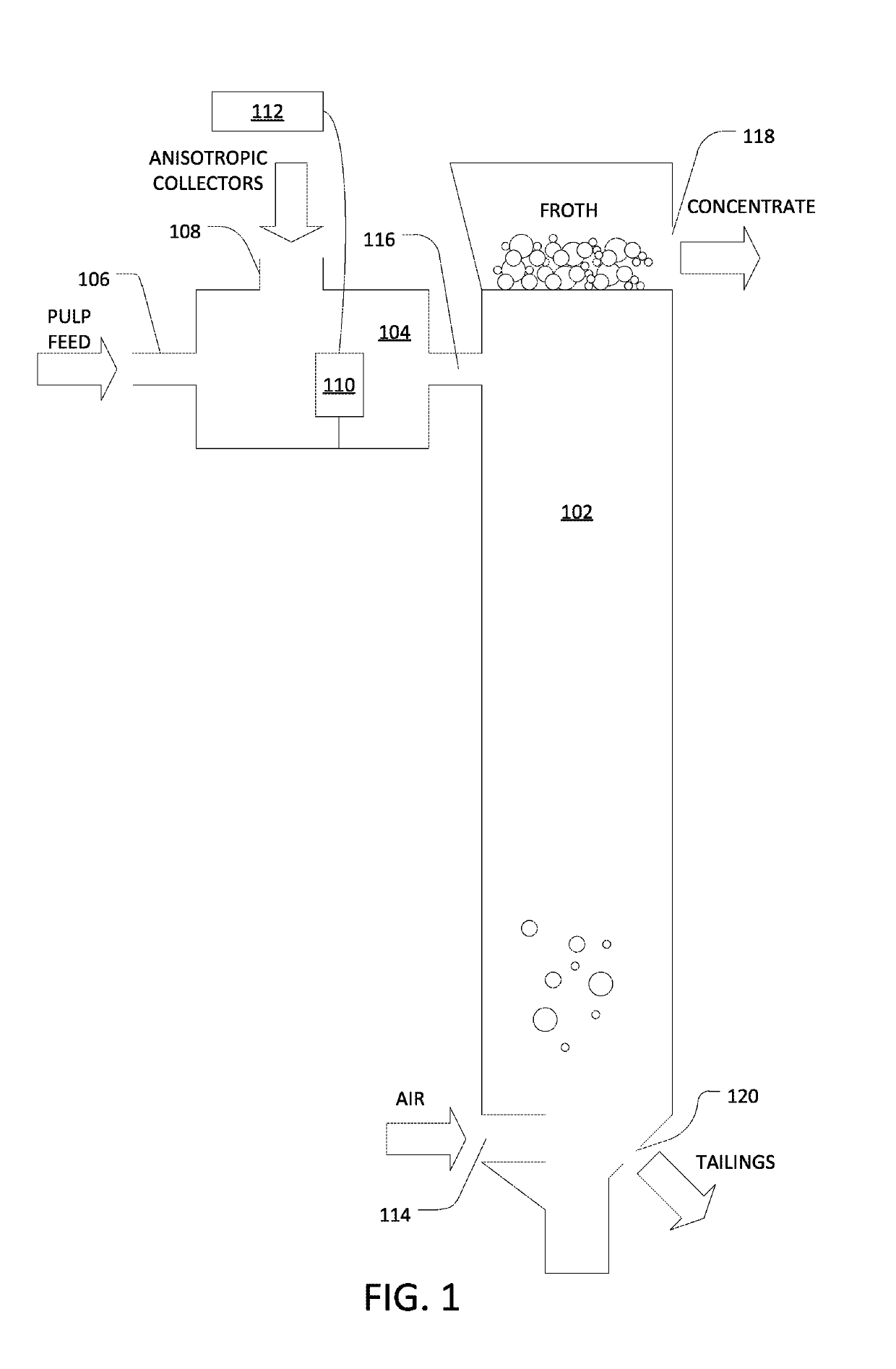
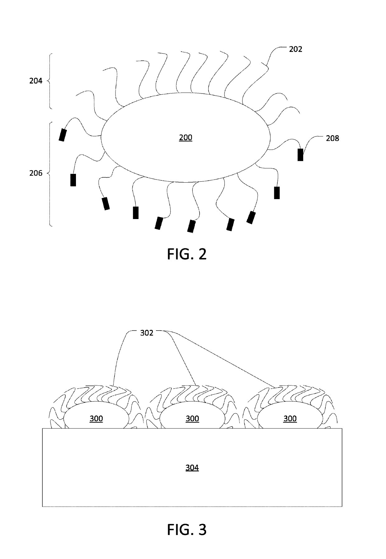
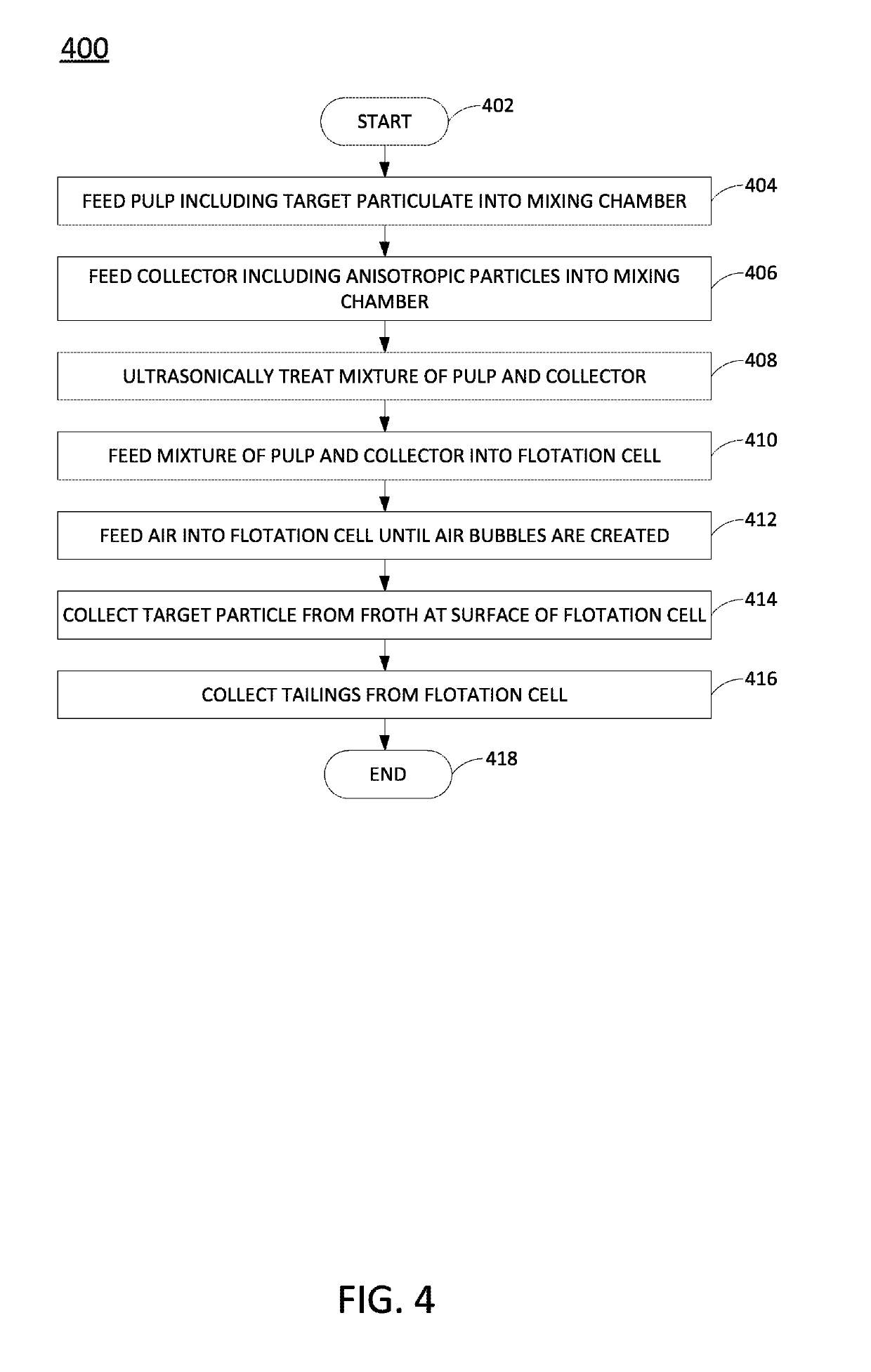
[0012]In one example, a method and apparatus for froth flotation using anisotropic particle collectors is disclosed. As discussed above, conventional froth flotation processes pass air bubbles through an aqueous suspension of pulp and, optionally, collectors in order to facilitate the separation of target particles from unwanted materials. The efficacy of the separation achieved by the froth flotation process can be significantly impacted by the selection of the collector, which selectively hydrophobizes the target minerals to be collected. The general composition of a conventional molecular collector is a homogenous hydrocarbon chain having a reactive or functional head group. The head group reacts with the target mineral surface, while the hydrocarbon chain is orientated away from the target mineral surface, toward the aqueous suspension for subsequent attachment to an air bubble.

[0013]In some cases, nanoparticles can be used as collectors. These nanoparticles may be treated with ...


PUM

PropertyMeasurementUnit
hydrophobicaaaaaaaaaa
hydrophilicaaaaaaaaaa
surface structureaaaaaaaaaa

Abstract

In one example, a method includes providing a pulp composed of a combination of particulate materials including particles of a target material. The pulp is mixed with a collector composed of anisotropic particles having at least two separate spatial domains that have different physiochemical properties, and the mixture of pulp and collector is fed into an aqueous solution containing air bubbles.

Description

FIELD OF THE DISCLOSURE[0001]The present disclosure relates generally to froth flotation and relates more specifically to froth flotation techniques that are aided by the use of collectors.BACKGROUND OF THE DISCLOSURE[0002]Froth flotation is a process that is used in many industries for selectively separating hydrophobic and hydrophilic materials. Generally, the process works by passing air bubbles through an aqueous suspension of a “pulp” that contains the materials to be separated (e.g., target mineral particles and unwanted material). Through conditioning of the target mineral particles, it is possible to induce preferential attachment of the target mineral particles to the air bubbles. The air bubbles and attached mineral particles float to the surface of the aqueous suspension as “froth” (which may be subsequently removed), whereas the unwanted material does not float to the surface and becomes the “tailings” of the process.[0003]In some cases, small molecules called “collector...

Claims


Application Information

Patent Timeline
Patent Type & Authority Patents(United States)
IPC IPC(8): B03D1/006B03D1/02B03D1/12
CPCB03D1/12B03D1/006B03D1/023B03D2201/02
Inventor BALDAUF, JULIABOJOVSCHI, ALEXEMASHFORD, BENJAMIN S.SCHIEBER, CHRISTINEYIAPANIS, GEORGE
Owner INT BUSINESS MASCH CORP
Why Eureka
Try Eureka