Adaptive coding for lidar systems

a lidar system and adaptive coding technology, applied in the field of adaptive coding for lidar systems, can solve the problems of inability to adapt to the environment, inability to detect and detect objects, and inability to accurately measure distance, so as to avoid cross-talk across different channels and/or interference, minimize the impact of unintended signals, and improve the resistance to environmental noise

Active Publication Date: 2019-11-05
HESAI TECH CO LTD
View PDF18 Cites 43 Cited by
  • Summary
  • Abstract
  • Description
  • Claims
  • Application Information

AI Technical Summary

Benefits of technology

[0004]A need exists for improved Lidar system for three-dimensional measurement. A further need exists for a Lidar system with encoded signals or encoded pulses of light beams to avoid cross-talk across different channels and / or interference between different Lidar systems. The provided Lidar system may address the above needs by employing an adaptive coding scheme or coding mechanism. The provided Lidar may have improved resistance to environmental noise. In particular, the coding scheme may change dynamically according real-time conditions. Different coding schemes may be selected based on an environment condition, signal condition and various others to minimize the impact of unintended signals or to better distinguish from unintended signals. Additionally, different coding schemes may be selected for improved energy efficiency. Three-dimensional imaging may be achieved by the provided Lidar system with improved accuracy and better performance.

Problems solved by technology

In some cases, confusion between return pulses may occur which may introduce incorrect measurements of distance.
For example, scattered light from another pulse transmitted by the same Lidar system or by a second Lidar system in proximity to the LiDAR system may mistakenly be paired with the original pulse light, which may lead to an incorrect measurement.
Additionally, range and accuracy of Lidar systems can be limited by environmental noise, cross talk between multiple Lidar sensors, and instrumental noise in the detected signal.

Method used


Image

  • Adaptive coding for lidar systems
  • Adaptive coding for lidar systems
  • Adaptive coding for lidar systems

Examples


Embodiment Construction

[0026]While preferable embodiments of the invention have been shown and described herein, it will be obvious to those skilled in the art that such embodiments are provided by way of example only. Numerous variations, changes, and substitutions will now occur to those skilled in the art without departing from the invention. It should be understood that various alternatives to the embodiments of the invention described herein may be employed in practicing the invention.

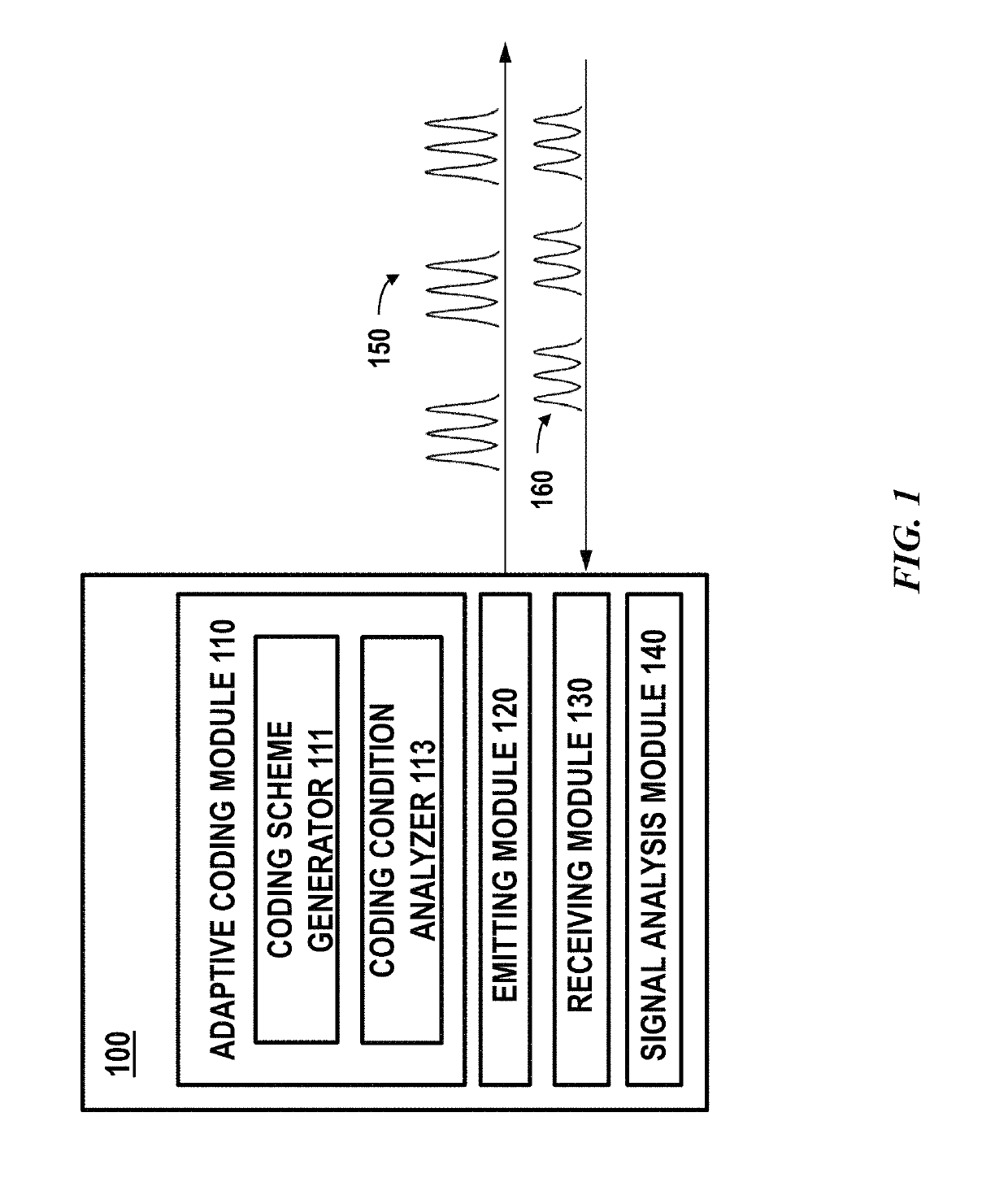
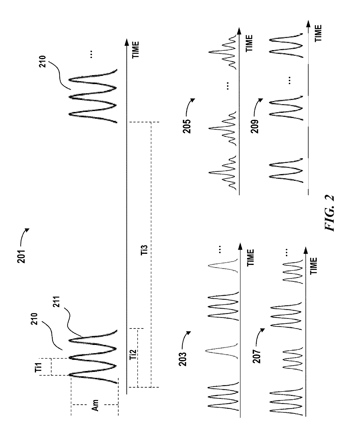
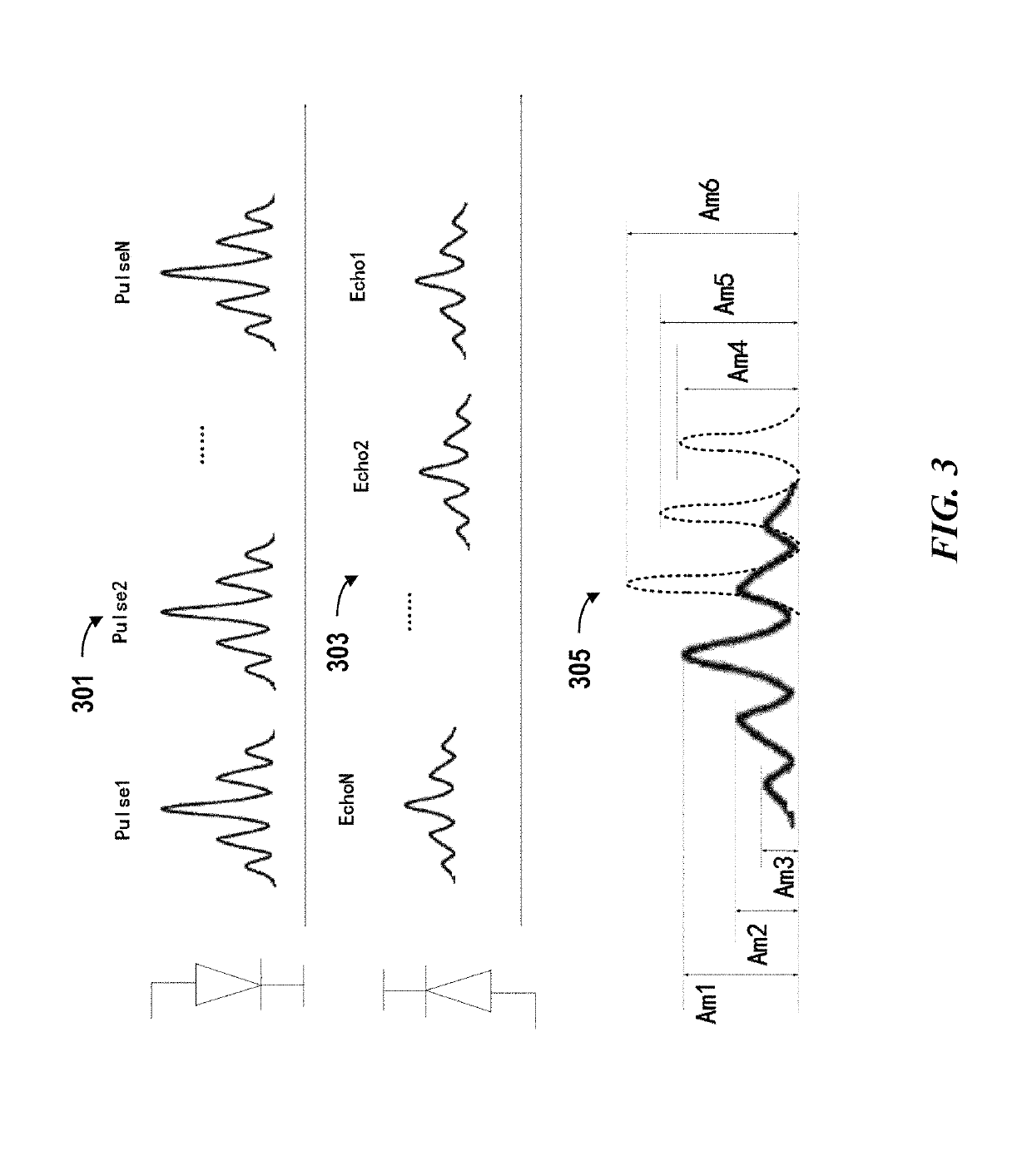
[0027]Lidar is a type of ranging sensor characterized by long detection distance, high resolution, and low interference by the environment. Lidar has been widely applied in the fields of intelligent robots, unmanned aerial vehicles, autonomous driving or self-driving. The working principle of Lidar is estimating a distance based on a round trip time (e.g., time of flight) of electromagnetic waves between a source and a target.

[0028]Incorrect measurements may occur when an unwanted signal, signal generated by exogenous s...


PUM


Abstract

A Lidar system is provided. The Lidar system comprise: a light source configured to emit a multi-pulse sequence to measure a distance between the Lidar system and a location in a three-dimensional environment, and the multi-pulse sequence comprises multiple pulses having a temporal profile; a photosensitive detector configured to detect light pulses from the three-dimensional environment; and one or more processors configured to: determine a coding scheme comprising the temporal profile, wherein the coding scheme is determined dynamically based on one or more real-time conditions including an environment condition, a condition of the Lidar system or a signal environment condition; and calculate the distance based on a time of flight of a sequence of detected light pulses, wherein the time of flight is determined by determining a match between the sequence of detected light pulses and the temporal profile.

Description

CROSS-REFERENCE[0001]This application is a Continuation Application of International PCT Application No. PCT / CN2018 / 109049, filed on Sep. 30, 2018, which claims the benefit of Chinese Application No. CN201810678690.4, filed Jun. 27, 2018, each of which is entirely incorporated herein by reference.BACKGROUND OF THE INVENTION[0002]Lidar (light detection and ranging) technology can be used to obtain three-dimensional information of an environment by measuring distances to objects. A Lidar system may include at least a light source configured to emit a pulse of light and a detector configured to receive returned pulse of light. The returned pulse of light or light beam may be referred to as echo light beam. Based on the lapse time between the emission of the pulse of light and detection of returned pulse of light (i.e., time of flight), a distance can be obtained. The pulse of light can be generated by a laser emitter then focused through a lens or lens assembly. The returned pulse of l...

Claims


Application Information

Patent Timeline
Patent Type & Authority Patents(United States)
IPC IPC(8): G01C3/08G01S7/486G01S7/487G01S17/10G01S7/4865
CPCG01S7/4865G01S7/4873G01S17/10G01S7/4817G01S7/487
Inventor ZHU, XUEZHOUXIANG, SHAOQING
Owner HESAI TECH CO LTD
Why Eureka
Try Eureka